
OPERATOR'S MANUAL

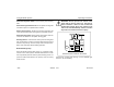
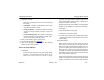

Table Of Contents
- How to Use This Manual
- Safety Signals
- Vehicle Safety
- How to Find What You Want
- A Special Word About Repairs
- Shop Manuals
- Preventive Maintenance Section
- Additional Sources of Information
- Start–Up
- Instruments and Controls
- Introduction
- Warning Lights and Buzzer
- Self Test
- Speedometer and Odometer
- Tachometer
- Coolant (Water) Temperature Gauge
- Engine Oil Pressure Gauge
- Dual Air Pressure Gauge (Air Reservoir)
- Fuel Gauge
- Voltmeter (option)
- Transmission Temperature Gauge (option)
- Air Filter Restriction Indicator (option)
- Headlight Switch
- Daytime Running Lights (option)
- Panel Lights
- ID and Clearance Lights
- Windshield Wipers/Washer
- Ignition Key Switch
- Parking Brake
- Cruise Control Switch
- Hand Throttle Control
- Heating and Air Conditioning
- Accessories
- Seats
- Steering Column and Mirrors
- Operating the Engine
- Operating the Transmission
- Using the Brake System
- Operating the Rear/Drive Axle
- More Driving Tips and Techniques
- Vehicle Recovery and Spring Brakes
- Shut–Down
- Introduction
- Maintenance Schedule and Lubrication
- Engine Maintenance
- Cooling System
- Brake System
- Air System
- Tires and Wheels
- Heater and Air Conditioner
- Electrical System
- Cab Maintenance
- Transmission and Clutch
- Steering and Driveline
- Front Axle and Suspension
- Rear Axle and Suspension
- Frame and Fifth Wheel
- Noise and Emission Control
- Consumer Information and Vehicle Identification

Using the Brake System Operating Instructions
– 90 –
PB1318 3/01 Model 330
vehicle. Be sure to be in the right gear before you
start down a hill, especially if you have a manual
transmission. You could get hung up in NEUTRAL
and lose the benefit of engine braking. “Coasting” is
illegal, and also VERY dangerous.
Anti-Lock Braking System
This vehicle is equipped with an Anti-Lock Braking System
(ABS). ABS reduces the likelihood of a wheel locking. If a
wheel is about to lock during braking, the ABS will automati-
cally adjust hydraulic pressure to the brake calipers on the
appropriate wheel(s) to prevent wheel lock-up. The ABS is
automatically activated when the ignition switch is turned on.
Hydraulic fluid from the primary and secondary master cylin-
der chambers feeds the (ABS) modulator valve body. Simul-
taneously, the vehicle's ABS system detects wheel speeds.
The sensors generate signals that are transmitted to an Elec-
tronic Control Unit (ECU). If the wheels start to lock, the ECU
signals the modulator assembly to regulate the brake pres-
sure of each locking wheel.
WARNING! Do not replace wheels or tires with a
different size than originally installed. The Anti-
Lock Brake System (ABS) is calibrated for the
specific tire revolutions per mile. Use of a differ-
ent tire and/or wheel size may cause the ABS
system to not function during a hard braking
event. This could cause an accident or serious
personal injury. See “Wheel and Tire Replace-
ment for Trucks with Hydraulic Brakes” on page
182 to determine the acceptable range of tire rev/
mile.
ABS Warning Lamp
The ABS warning lamp will come on briefly, then go off, when
the key switch is first turned on. If the lamp remains ON until
a speed of 4 mph (6 km/h) is reached, then goes OFF, there
may be a stored fault code. If the lamp remains ON when a
speed in excess of 4 mph (6 km/h) is reached, there may be
an active fault in the ABS system.
CAUTION: If the ABS warning light does not illu-
minate when the ignition is first turned on, there
is a problem with the bulb or wiring. You should
have this checked as soon as possible.