
OPERATOR'S MANUAL

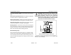
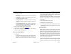

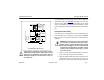
Table Of Contents
- How to Use This Manual
- Safety Signals
- Vehicle Safety
- How to Find What You Want
- A Special Word About Repairs
- Shop Manuals
- Preventive Maintenance Section
- Additional Sources of Information
- Start–Up
- Instruments and Controls
- Introduction
- Warning Lights and Buzzer
- Self Test
- Speedometer and Odometer
- Tachometer
- Coolant (Water) Temperature Gauge
- Engine Oil Pressure Gauge
- Dual Air Pressure Gauge (Air Reservoir)
- Fuel Gauge
- Voltmeter (option)
- Transmission Temperature Gauge (option)
- Air Filter Restriction Indicator (option)
- Headlight Switch
- Daytime Running Lights (option)
- Panel Lights
- ID and Clearance Lights
- Windshield Wipers/Washer
- Ignition Key Switch
- Parking Brake
- Cruise Control Switch
- Hand Throttle Control
- Heating and Air Conditioning
- Accessories
- Seats
- Steering Column and Mirrors
- Operating the Engine
- Operating the Transmission
- Using the Brake System
- Operating the Rear/Drive Axle
- More Driving Tips and Techniques
- Vehicle Recovery and Spring Brakes
- Shut–Down
- Introduction
- Maintenance Schedule and Lubrication
- Engine Maintenance
- Cooling System
- Brake System
- Air System
- Tires and Wheels
- Heater and Air Conditioner
- Electrical System
- Cab Maintenance
- Transmission and Clutch
- Steering and Driveline
- Front Axle and Suspension
- Rear Axle and Suspension
- Frame and Fifth Wheel
- Noise and Emission Control
- Consumer Information and Vehicle Identification

Operating Instructions Using the Brake System
Model 330 PB1318 3/01
– 87 –
Brake Components
The following is a brief description of the hydraulic brake sys-
tem. It is intended to supply you with general information on
how the system works. For complete information see the
Peterbilt Medium Duty Maintenance Manual.
Anti-Lock Brake System (ABS) Modulator Valve Body:
adjusts brake fluid flow between the master cylinder and the
wheel calipers to avoid wheel lockup.
ABS Warning Lamp: lights when the ABS controller detects
wheel lock-up while driving and activates the ABS. Lights
also when a fault in the ABS is detected.
Brake Fluid Reservoir: stores brake fluid and offers a place
to replenish when needed.
Brake Master Cylinder: translates brake pedal force into
hydraulic fluid pressure in the primary and secondary cir-
cuits.
Brake Pedal: applies actuation force from operator’s foot to
the master cylinder pistons.
Brake Warning Lamp: illuminates when either power steer-
ing fluid flow is interrupted or when a pressure differential is
present in the primary and secondary brake fluid pressure.
Either case adversely affects braking operation.
Differential Switch: measures the hydraulic fluid pressure
difference between the primary and secondary circuits.
Electrohydraulic Pump: The Electrohydraulic (EH) pump is
used as a backup boost pump. The EH pump turns on and
provides fluid pressure to the hydraulic booster in the event
power steering fluid stops flowing through the booster head.
Front and Rear Wheel Calipers: translate hydraulic fluid
pressure into force applied at each wheel-end brake rotor to
retard wheel motion.
Hydraulic Booster: The hydraulic booster applies additional
hydraulic force from the power steering gear to the master
cylinder piston when the brake pedal is applied.
Parking Brake Lamp: illuminates when the parking brake is
engaged (the lever is in the up position.)
Parking Brake Lever: the hand lever located in the cab
which engages or disengages the driveline drum brake.