
OPERATOR'S MANUAL

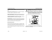
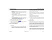

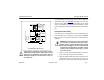
Table Of Contents
- How to Use This Manual
- Safety Signals
- Vehicle Safety
- How to Find What You Want
- A Special Word About Repairs
- Shop Manuals
- Preventive Maintenance Section
- Additional Sources of Information
- Start–Up
- Instruments and Controls
- Introduction
- Warning Lights and Buzzer
- Self Test
- Speedometer and Odometer
- Tachometer
- Coolant (Water) Temperature Gauge
- Engine Oil Pressure Gauge
- Dual Air Pressure Gauge (Air Reservoir)
- Fuel Gauge
- Voltmeter (option)
- Transmission Temperature Gauge (option)
- Air Filter Restriction Indicator (option)
- Headlight Switch
- Daytime Running Lights (option)
- Panel Lights
- ID and Clearance Lights
- Windshield Wipers/Washer
- Ignition Key Switch
- Parking Brake
- Cruise Control Switch
- Hand Throttle Control
- Heating and Air Conditioning
- Accessories
- Seats
- Steering Column and Mirrors
- Operating the Engine
- Operating the Transmission
- Using the Brake System
- Operating the Rear/Drive Axle
- More Driving Tips and Techniques
- Vehicle Recovery and Spring Brakes
- Shut–Down
- Introduction
- Maintenance Schedule and Lubrication
- Engine Maintenance
- Cooling System
- Brake System
- Air System
- Tires and Wheels
- Heater and Air Conditioner
- Electrical System
- Cab Maintenance
- Transmission and Clutch
- Steering and Driveline
- Front Axle and Suspension
- Rear Axle and Suspension
- Frame and Fifth Wheel
- Noise and Emission Control
- Consumer Information and Vehicle Identification

Using the Brake System Operating Instructions
– 86 –
PB1318 3/01 Model 330
the parking brake valve will not hold in the release position
until the system pressure exceeds 60 psi (414 kPa), which is
the pressure required to override the load of this valve’s
plunger return spring.
Trailer Supply Valve (tractor): The Red octagonal-shaped
knob protects the tractor system; it functions in conjunction
with the parking brake valve (yellow). The trailer supply valve
is responsible for synchronizing the tractor and trailer parking
and emergency brakes. If the air system is being charged
from zero pressure, the trailer supply valve will not hold in the
applied position until the system pressure exceeds 50 psi
(345 kPa). It automatically pops out and exhausts air if supply
air pressure drops below 60 psi (414 kPa).
Tractor Protection Valve: The functions of this valve are to
(1) receive all pneumatic signals pertinent to the operation of
the trailer brake system, (2) transmit these signals to the
trailer, and (3) protect the tractor air supply in case of separa-
tion of the air lines connecting the tractor to the trailer.
Hydraulic Brakes
Introduction
The operation of the vehicle’s braking system is based on the
principle of hydraulics. Hydraulic action begins when force is
applied to the brake pedal. This force creates hydraulic pres-
sure in the master cylinder and is amplified with assistance of
a power booster. The supplemental boost in force is devel-
oped when pressurized power steering fluid from the steering
pump presses on the master cylinder piston. As a safety pre-
caution, the pressurized fluid from the master cylinder has
two mutually independent circuits. The primary circuit sup-
plies the front wheels while the secondary circuit supplies the
rear wheels. The displaced fluid from the master cylinder
travels through brake pipes terminating at the wheel cylin-
ders which actuate the brake pad mechanisms. Actuation of
these mechanisms force the brake pads against the rotors to
stop the wheels.
A reserve electric motor pump provides a redundant power
source for the hydraulic booster in the event normal flow from
the power steering pump is interrupted. Manual braking is
also available in the event both the power and reserve sys-
tems are inoperative.