
OPERATOR'S MANUAL

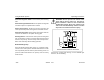
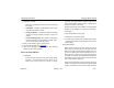

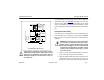
Table Of Contents
- How to Use This Manual
- Safety Signals
- Vehicle Safety
- How to Find What You Want
- A Special Word About Repairs
- Shop Manuals
- Preventive Maintenance Section
- Additional Sources of Information
- Start–Up
- Instruments and Controls
- Introduction
- Warning Lights and Buzzer
- Self Test
- Speedometer and Odometer
- Tachometer
- Coolant (Water) Temperature Gauge
- Engine Oil Pressure Gauge
- Dual Air Pressure Gauge (Air Reservoir)
- Fuel Gauge
- Voltmeter (option)
- Transmission Temperature Gauge (option)
- Air Filter Restriction Indicator (option)
- Headlight Switch
- Daytime Running Lights (option)
- Panel Lights
- ID and Clearance Lights
- Windshield Wipers/Washer
- Ignition Key Switch
- Parking Brake
- Cruise Control Switch
- Hand Throttle Control
- Heating and Air Conditioning
- Accessories
- Seats
- Steering Column and Mirrors
- Operating the Engine
- Operating the Transmission
- Using the Brake System
- Operating the Rear/Drive Axle
- More Driving Tips and Techniques
- Vehicle Recovery and Spring Brakes
- Shut–Down
- Introduction
- Maintenance Schedule and Lubrication
- Engine Maintenance
- Cooling System
- Brake System
- Air System
- Tires and Wheels
- Heater and Air Conditioner
- Electrical System
- Cab Maintenance
- Transmission and Clutch
- Steering and Driveline
- Front Axle and Suspension
- Rear Axle and Suspension
- Frame and Fifth Wheel
- Noise and Emission Control
- Consumer Information and Vehicle Identification

Operating Instructions Using the Brake System
Model 330 PB1318 3/01
– 85 –
The wet tank receives air from the air dryer and cools it
somewhat, allowing moisture to condense for draining. Rela-
tively dry air is then supplied to the two service tanks for dis-
tribution to their respective brake circuits. The service tanks
are isolated from each other by check valves.
Dual Service Brake Treadle Valve: delivers air to the two
service brake circuits.
Double Check Valve: directs the higher air pressure from
either the rear (primary) or front (secondary) service tank to
the modulating valve.
Modulating Valve (SR–1): used only on full trucks, not trac-
tors. It performs four functions:
• Limits spring brake hold-off air pressure delivered to the
spring brake chambers.
• Provides a quick release of air pressure from the spring
brake chambers to speed spring brake application.
• Modulates spring brake application in proportion to front
service application in the event of a rear service failure.
• Prevents compounding of service and spring applica-
tions.
Relay valve (full truck): speeds up the application of the
rear service brake. It also incorporates a quick–release fea-
ture.
Brake Proportioning (BP-R1) valve (tractor): this valve
delivers air to the tractor's service brake chambers. It auto-
matically proportions the drive axle brake app
lication pressure when driving bobtail (without a trailer con-
nected). Proportioning the brakes allows full use of the steer
axle brakes and reduces lockup of the drive axle brakes. The
bobtail brake proportioning system is automatically turned off
when a trailer is connected.
Quick–Release Valve:
speeds the release of air from the
brake chambers. When air is released, the air in the brake
chambers is exhausted at the quick-release valve, rather
than exhausting back through the treadle valve.
Single Check Valve: allows air flow in one direction only.
Parking Brake Valve: yellow diamond-shaped knob. It con-
trols the application and release of the parking (spring)
brakes of truck or tractor-trailer combinations or of the tractor
alone. If the air system is being charged from zero pressure,