
OPERATOR'S MANUAL

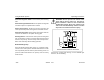
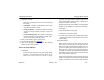

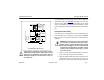
Table Of Contents
- How to Use This Manual
- Safety Signals
- Vehicle Safety
- How to Find What You Want
- A Special Word About Repairs
- Shop Manuals
- Preventive Maintenance Section
- Additional Sources of Information
- Start–Up
- Instruments and Controls
- Introduction
- Warning Lights and Buzzer
- Self Test
- Speedometer and Odometer
- Tachometer
- Coolant (Water) Temperature Gauge
- Engine Oil Pressure Gauge
- Dual Air Pressure Gauge (Air Reservoir)
- Fuel Gauge
- Voltmeter (option)
- Transmission Temperature Gauge (option)
- Air Filter Restriction Indicator (option)
- Headlight Switch
- Daytime Running Lights (option)
- Panel Lights
- ID and Clearance Lights
- Windshield Wipers/Washer
- Ignition Key Switch
- Parking Brake
- Cruise Control Switch
- Hand Throttle Control
- Heating and Air Conditioning
- Accessories
- Seats
- Steering Column and Mirrors
- Operating the Engine
- Operating the Transmission
- Using the Brake System
- Operating the Rear/Drive Axle
- More Driving Tips and Techniques
- Vehicle Recovery and Spring Brakes
- Shut–Down
- Introduction
- Maintenance Schedule and Lubrication
- Engine Maintenance
- Cooling System
- Brake System
- Air System
- Tires and Wheels
- Heater and Air Conditioner
- Electrical System
- Cab Maintenance
- Transmission and Clutch
- Steering and Driveline
- Front Axle and Suspension
- Rear Axle and Suspension
- Frame and Fifth Wheel
- Noise and Emission Control
- Consumer Information and Vehicle Identification

Using the Brake System Operating Instructions
– 84 –
PB1318 3/01 Model 330
• After the engine is started, warmed up, and you are
ready to get under way, turn the exhaust brake switch
ON for added braking effect.
WARNING! Do not use the engine retarder when
operating on road surfaces with poor traction
(such as wet, icy, or snow covered roads or
gravel). Retarders can cause the wheels to skid
on a slippery surface. You could lose control of
the vehicle and/or jackknife if the wheels begin
to skid, resulting in an accident.
However, if your vehicle is equipped with Rockwell/WABCO
anti-lock brakes (ABS), the operation of the exhaust brake (if
turned ON) will be controlled by the ABS. For more ABS
information, see
“Anti-Lock Braking System” on page 79
.
For further details on how to use the exhaust brake, see the
exhaust brake manufacturer’s
Owner’s Manual
.
Brake Components
The following is a brief description of the air/brake system. It
is intended to supply you with general information on how the
system works. For complete information see the Medium
Duty Maintenance Manual.
Compressor: supplies air to the system. System pressure is
controlled by the governor.
Governor: controls the air pressure in the system by actuat-
ing the compressor discharge mechanism. Its cut-out pres-
sure is 115 to 125 psi (793 to 862 kPa). Its preset cut-in
pressure is set to between 13 to 25 psi (90 to 172 kPa) below
the cut-out pressure setting (cut-out and cut-in interval is not
adjustable).
Safety Valve: installed on the supply reservoir outlet. It
should “vent off” at 150 psi (1034 kPa) permitting air to
escape.
Air Dryer (Option): collects and removes moisture and con-
taminants from the air as it travels from the compressor to the
wet tank (reservoir).
Compressed Air Tanks: The wet (supply) and dry (service)
tanks are located behind the battery box and on the frame
rail; the supply tank is below the front service tank. See “Air
Tanks” on
page 165
.