
OPERATOR'S MANUAL
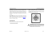
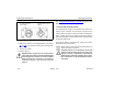
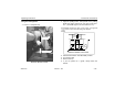
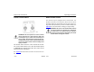


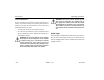
Table Of Contents
- How to Use This Manual
- Safety Signals
- Vehicle Safety
- How to Find What You Want
- A Special Word About Repairs
- Shop Manuals
- Preventive Maintenance Section
- Additional Sources of Information
- Start–Up
- Instruments and Controls
- Introduction
- Warning Lights and Buzzer
- Self Test
- Speedometer and Odometer
- Tachometer
- Coolant (Water) Temperature Gauge
- Engine Oil Pressure Gauge
- Dual Air Pressure Gauge (Air Reservoir)
- Fuel Gauge
- Voltmeter (option)
- Transmission Temperature Gauge (option)
- Air Filter Restriction Indicator (option)
- Headlight Switch
- Daytime Running Lights (option)
- Panel Lights
- ID and Clearance Lights
- Windshield Wipers/Washer
- Ignition Key Switch
- Parking Brake
- Cruise Control Switch
- Hand Throttle Control
- Heating and Air Conditioning
- Accessories
- Seats
- Steering Column and Mirrors
- Operating the Engine
- Operating the Transmission
- Using the Brake System
- Operating the Rear/Drive Axle
- More Driving Tips and Techniques
- Vehicle Recovery and Spring Brakes
- Shut–Down
- Introduction
- Maintenance Schedule and Lubrication
- Engine Maintenance
- Cooling System
- Brake System
- Air System
- Tires and Wheels
- Heater and Air Conditioner
- Electrical System
- Cab Maintenance
- Transmission and Clutch
- Steering and Driveline
- Front Axle and Suspension
- Rear Axle and Suspension
- Frame and Fifth Wheel
- Noise and Emission Control
- Consumer Information and Vehicle Identification

Heating and Air Conditioning Operating Instructions
– 38 –
PB1318 3/01 Model 330
erant leak on your vehicle, have your system
serviced immediately and observe the following pre-
cautions:
– Stay away from the hot engine until the exhaust
manifold has cooled.
– Do not permit any open flame in the area. Even a
match or a cigarette lighter may generate a haz-
ardous quantity of poisonous gas.
– Do not smoke in the area. Inhaling gaseous
refrigerant through a cigarette may cause violent
illness.
Controls
The heater and air conditioning control unit is mounted in the
center dash console, below the radio. The standard control
unit has four controls to regulate air flow and temperature in
the cab: fan speed switch (A), air directional control switch
(B), air temperature switch (C), and air circulating mode
switch (D). With optional air conditioning, a fifth switch (E) is
used.
Fan Speed Control
The fan speed rotary switch (A) allows you to select one of
four blower speeds (1-4).
Air Direction Control
The air direction rotary switch (B) controls the air movement
within the cab. Five modes direct the air flow to the three sets
of air outlets: front panel, floor, and window defrost:
1.Front Panel only
2.Panel and Floor (Bi-level)
3.Floor only
4.Defrost and Floor (Bi-level)
5.Defrost only
Temperature Control
The temperature rotary switch (C) allows you to adjust and
maintain a comfortable internal cab temperature.
Air Circulation Control
The air circulation rocker switch (D) allows you to select
FRESH air from outside the cab or recirculate (RECIRC) air
from within the cab.
Air Conditioner Control
The optional air conditioner is engaged with this rocker
switch (E).