
OPERATOR'S MANUAL
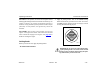
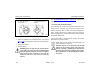
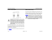


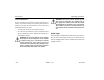
Table Of Contents
- How to Use This Manual
- Safety Signals
- Vehicle Safety
- How to Find What You Want
- A Special Word About Repairs
- Shop Manuals
- Preventive Maintenance Section
- Additional Sources of Information
- Start–Up
- Instruments and Controls
- Introduction
- Warning Lights and Buzzer
- Self Test
- Speedometer and Odometer
- Tachometer
- Coolant (Water) Temperature Gauge
- Engine Oil Pressure Gauge
- Dual Air Pressure Gauge (Air Reservoir)
- Fuel Gauge
- Voltmeter (option)
- Transmission Temperature Gauge (option)
- Air Filter Restriction Indicator (option)
- Headlight Switch
- Daytime Running Lights (option)
- Panel Lights
- ID and Clearance Lights
- Windshield Wipers/Washer
- Ignition Key Switch
- Parking Brake
- Cruise Control Switch
- Hand Throttle Control
- Heating and Air Conditioning
- Accessories
- Seats
- Steering Column and Mirrors
- Operating the Engine
- Operating the Transmission
- Using the Brake System
- Operating the Rear/Drive Axle
- More Driving Tips and Techniques
- Vehicle Recovery and Spring Brakes
- Shut–Down
- Introduction
- Maintenance Schedule and Lubrication
- Engine Maintenance
- Cooling System
- Brake System
- Air System
- Tires and Wheels
- Heater and Air Conditioner
- Electrical System
- Cab Maintenance
- Transmission and Clutch
- Steering and Driveline
- Front Axle and Suspension
- Rear Axle and Suspension
- Frame and Fifth Wheel
- Noise and Emission Control
- Consumer Information and Vehicle Identification

Operating Instructions Heating and Air Conditioning
Model 330 PB1318 3/01
– 37 –
HEATING AND AIR CONDITIONING
Introduction
WARNING! Do not drive with your visibility
reduced by fog, condensation, or frost on the
windshield. Your view may be obscured, which
could result in an injury accident. For clear visi-
bility and safe driving it is extremely important
for you to follow the instructions on the use of
the ventilation/heating and defogging/defrosting
system. If in doubt, consult your dealer. Maxi-
mum heating output and fast defrosting can be
obtained only after the engine has reached oper-
ating temperature.
Internal air circulation control is provided by three sets of
outlets:
• Front outlets on the dashboard panel, with directional
louvers
• Floor outlets under the dashboard
• Window defrost vents on the dashboard
WARNING! Excessive heat may cause the pres-
surized components of the air conditioning sys-
tem to explode. Never weld, solder, steam clean,
or use a blow torch near any part of the air con-
ditioning system.
• If a refrigerant leak develops in the presence of
excessive heat or an open flame, hazardous gases
may be generated. These gases may cause uncon-
sciousness or death. If you become aware of a refrig-
Heater and Air Conditioner Controls
02593
FRESH
RECIRC
AC
ONOFF
1
2
3
4
0
D
E
A
B
C