
OPERATOR'S MANUAL


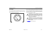

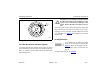


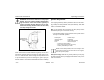
Table Of Contents
- How to Use This Manual
- Safety Signals
- Vehicle Safety
- How to Find What You Want
- A Special Word About Repairs
- Shop Manuals
- Preventive Maintenance Section
- Additional Sources of Information
- Start–Up
- Instruments and Controls
- Introduction
- Warning Lights and Buzzer
- Self Test
- Speedometer and Odometer
- Tachometer
- Coolant (Water) Temperature Gauge
- Engine Oil Pressure Gauge
- Dual Air Pressure Gauge (Air Reservoir)
- Fuel Gauge
- Voltmeter (option)
- Transmission Temperature Gauge (option)
- Air Filter Restriction Indicator (option)
- Headlight Switch
- Daytime Running Lights (option)
- Panel Lights
- ID and Clearance Lights
- Windshield Wipers/Washer
- Ignition Key Switch
- Parking Brake
- Cruise Control Switch
- Hand Throttle Control
- Heating and Air Conditioning
- Accessories
- Seats
- Steering Column and Mirrors
- Operating the Engine
- Operating the Transmission
- Using the Brake System
- Operating the Rear/Drive Axle
- More Driving Tips and Techniques
- Vehicle Recovery and Spring Brakes
- Shut–Down
- Introduction
- Maintenance Schedule and Lubrication
- Engine Maintenance
- Cooling System
- Brake System
- Air System
- Tires and Wheels
- Heater and Air Conditioner
- Electrical System
- Cab Maintenance
- Transmission and Clutch
- Steering and Driveline
- Front Axle and Suspension
- Rear Axle and Suspension
- Frame and Fifth Wheel
- Noise and Emission Control
- Consumer Information and Vehicle Identification

Operating Instructions Instruments and Controls
Model 330 PB1318 3/01
– 25 –
3. Place the transmission in park and set the parking
brake. (See Pages
65
and
72
for transmission
shifting and parking brake information.)
4. Turn OFF the engine.
5. Turn ON the emergency flasher and use other
warning devices to alert other motorists.
6. Wait a few minutes to allow oil to drain into the
engine oil pan, and then check the oil level. (See
page 139
for details on checking oil level.)
7. Add oil if necessary. If the problem persists, con-
tact an Authorized Service Center.
For further information on operating your engine properly,
see
page 55
.
Dual Air Pressure Gauge (Air Reservoir)
The dual air pressure gauge indicates the amount of air pres-
sure in the brake system in pounds per square inch (psi). The
WHITE pointer shows the front (secondary service) reservoir
air pressure, and the ORANGE pointer indicates pressure in
the rear (primary service) reservoir.
If the pressure in either or both circuits is too low for normal
brake operation (below 64 psi), a warning light in the panel
will glow and the audible alarm will sound.
WARNING! If the light and alarm do not turn off
at start-up, do not try to drive the vehicle until
the problem is found and fixed.
Dual Air Pressure Gauge (Air Reservoir)
02581
REAR
PRIMARY
SERVICE
CIRCUIT
(ORANGE)
FRONT
SECONDARY
SERVICE
CIRCUIT
(WHITE)