
OPERATOR'S MANUAL
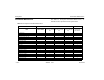
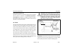
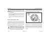
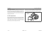
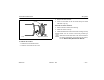
Table Of Contents
- How to Use This Manual
- Safety Signals
- Vehicle Safety
- How to Find What You Want
- A Special Word About Repairs
- Shop Manuals
- Preventive Maintenance Section
- Additional Sources of Information
- Start–Up
- Instruments and Controls
- Introduction
- Warning Lights and Buzzer
- Self Test
- Speedometer and Odometer
- Tachometer
- Coolant (Water) Temperature Gauge
- Engine Oil Pressure Gauge
- Dual Air Pressure Gauge (Air Reservoir)
- Fuel Gauge
- Voltmeter (option)
- Transmission Temperature Gauge (option)
- Air Filter Restriction Indicator (option)
- Headlight Switch
- Daytime Running Lights (option)
- Panel Lights
- ID and Clearance Lights
- Windshield Wipers/Washer
- Ignition Key Switch
- Parking Brake
- Cruise Control Switch
- Hand Throttle Control
- Heating and Air Conditioning
- Accessories
- Seats
- Steering Column and Mirrors
- Operating the Engine
- Operating the Transmission
- Using the Brake System
- Operating the Rear/Drive Axle
- More Driving Tips and Techniques
- Vehicle Recovery and Spring Brakes
- Shut–Down
- Introduction
- Maintenance Schedule and Lubrication
- Engine Maintenance
- Cooling System
- Brake System
- Air System
- Tires and Wheels
- Heater and Air Conditioner
- Electrical System
- Cab Maintenance
- Transmission and Clutch
- Steering and Driveline
- Front Axle and Suspension
- Rear Axle and Suspension
- Frame and Fifth Wheel
- Noise and Emission Control
- Consumer Information and Vehicle Identification

Preventive Maintenance Air System
Model 330 PB1318 3/01
– 165 –
Air System Function Test
Scheduled maintenance should be performed on the Model
330 air system, as outlined in the Medium Duty Mainte-
nance Manual and Table 11. In addition, perform an Air Sys-
tem Function Test at least every 3 months or if there is any
indication of a potential problem.
Air Tanks
The front (secondary) service tank is underneath the cab, on
the driver’s side; the wet (supply) tank is underneath the front
service tank, behind the battery box; and the rear (primary)
service tank is attached to the left frame, just behind the cab.
The supply tank (or “wet” tank), must be drained on a daily
basis. Drain the supply tank by pulling the drain valve lan-
yard. Hold it open until the escaping air is free of water.
The two service tanks (or “dry” tanks), must be drained on a
weekly basis. Drain the two service tanks by opening the
drain valves. Turn valve handles counter-clockwise, and
leave open until the escaping air is free of water.
WARNING! If the supply and service tanks are
not drained at the recommended frequency,
water could enter the air lines and valves. This
could cause corrosion or blockage, which could
compromise the brake system safety and poten-
tially cause an injury accident.
Periodically: Clean filter screens ahead of the valves by
removing the screens and soaking them in solvent. Blow
them dry with pressurized air before reinstalling them.
Location of Air Tanks
FRONT
SECONDARY
(SERVICE) TANK
DRAIN VALVE
WET (SUPPLY)
TANK UNDER
REAR PRIMARY
(SERVICE) TANK
02602
FRONT SERVICE
TANK