
OPERATOR'S MANUAL


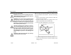
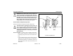
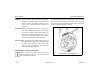

Table Of Contents
- How to Use This Manual
- Safety Signals
- Vehicle Safety
- How to Find What You Want
- A Special Word About Repairs
- Shop Manuals
- Preventive Maintenance Section
- Additional Sources of Information
- Start–Up
- Instruments and Controls
- Introduction
- Warning Lights and Buzzer
- Self Test
- Speedometer and Odometer
- Tachometer
- Coolant (Water) Temperature Gauge
- Engine Oil Pressure Gauge
- Dual Air Pressure Gauge (Air Reservoir)
- Fuel Gauge
- Voltmeter (option)
- Transmission Temperature Gauge (option)
- Air Filter Restriction Indicator (option)
- Headlight Switch
- Daytime Running Lights (option)
- Panel Lights
- ID and Clearance Lights
- Windshield Wipers/Washer
- Ignition Key Switch
- Parking Brake
- Cruise Control Switch
- Hand Throttle Control
- Heating and Air Conditioning
- Accessories
- Seats
- Steering Column and Mirrors
- Operating the Engine
- Operating the Transmission
- Using the Brake System
- Operating the Rear/Drive Axle
- More Driving Tips and Techniques
- Vehicle Recovery and Spring Brakes
- Shut–Down
- Introduction
- Maintenance Schedule and Lubrication
- Engine Maintenance
- Cooling System
- Brake System
- Air System
- Tires and Wheels
- Heater and Air Conditioner
- Electrical System
- Cab Maintenance
- Transmission and Clutch
- Steering and Driveline
- Front Axle and Suspension
- Rear Axle and Suspension
- Frame and Fifth Wheel
- Noise and Emission Control
- Consumer Information and Vehicle Identification

Preventive Maintenance Brake System
Model 330 PB1318 3/01
– 161 –
Anti–Lock Braking System (ABS)
Your Model 330 is equipped with an anti-lock braking system.
For detailed service information, see the Peterbilt Medium
Duty Maintenance Manual. All service work should be per-
formed by a qualified technician at an Authorized Service
Center. The foundation brake system must be in proper work-
ing order to ensure the best ABS performance.
CAUTION: Do not weld anywhere on the vehicle
before detaching the ABS Electronic Control Unit
(ECU) connector and all other electronic control
units. Welding equipment can send an energy
surge through electronic equipment and cause
damage. Disconnect all ECUs before attaching
welding equipment.
CAUTION: Never detach the ECU connector with
the ignition turned on. The connectors could arc
and damage electronic equipment. Turn off the
ignition before disconnecting any electronic
equipment.
Other precautions
• Check ABS wiring harnesses periodically for chafing or
other problems. No regular maintenance is required on
the ABS components.
• During wheel balancing, dyno testing, or any time the
ignition is on with part of the ABS disconnected, a failure
code will be recorded. Consult with your Peterbilt Dealer
or Authorized Service Center for information on clearing
the failure code.
If, due to operating conditions, a brake application causes
either wheel on the same axle to begin skidding, wheel
speed sensors immediately signal the anti-lock controller in
the modulator assembly. The controller responds instantly by
signaling the solenoids in the modulator which activate the air
valves, reducing application pressure as needed to prevent
the wheels from locking up. If this over-riding correction is
effective, application pressure is allowed to build up to the
original input.
Any malfunction of the anti-lock system on one or more axles
will cause the system to fail-safe, and the panel-mounted
amber warning light will come on, indicating both a malfunc-
tion, and automatic shut-down of the system. If the founda-
tion brake system is intact, the service brakes will continue to
function normally, but without benefit of the anti-lock feature.