
OPERATOR'S MANUAL
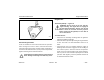
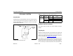


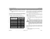
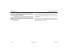
Table Of Contents
- How to Use This Manual
- Safety Signals
- Vehicle Safety
- How to Find What You Want
- A Special Word About Repairs
- Shop Manuals
- Preventive Maintenance Section
- Additional Sources of Information
- Start–Up
- Instruments and Controls
- Introduction
- Warning Lights and Buzzer
- Self Test
- Speedometer and Odometer
- Tachometer
- Coolant (Water) Temperature Gauge
- Engine Oil Pressure Gauge
- Dual Air Pressure Gauge (Air Reservoir)
- Fuel Gauge
- Voltmeter (option)
- Transmission Temperature Gauge (option)
- Air Filter Restriction Indicator (option)
- Headlight Switch
- Daytime Running Lights (option)
- Panel Lights
- ID and Clearance Lights
- Windshield Wipers/Washer
- Ignition Key Switch
- Parking Brake
- Cruise Control Switch
- Hand Throttle Control
- Heating and Air Conditioning
- Accessories
- Seats
- Steering Column and Mirrors
- Operating the Engine
- Operating the Transmission
- Using the Brake System
- Operating the Rear/Drive Axle
- More Driving Tips and Techniques
- Vehicle Recovery and Spring Brakes
- Shut–Down
- Introduction
- Maintenance Schedule and Lubrication
- Engine Maintenance
- Cooling System
- Brake System
- Air System
- Tires and Wheels
- Heater and Air Conditioner
- Electrical System
- Cab Maintenance
- Transmission and Clutch
- Steering and Driveline
- Front Axle and Suspension
- Rear Axle and Suspension
- Frame and Fifth Wheel
- Noise and Emission Control
- Consumer Information and Vehicle Identification

Preventive Maintenance Cooling System
Model 330 PB1318 3/01
– 145 –
COOLING SYSTEM
Introduction
Peterbilt Trucks are standard with Air-to-Air cooling systems.
These cooling systems incorporate a radiator to cool the
engine jacket water and a Charge-Air-Cooler to cool turbo-
charged engine intake air.
Radiator and Hose Clamps
Use torque values in Table 6 to check radiator and hose
clamps.
Topping Up
Check the coolant level after each trip when the engine has
cooled. The coolant level should be even with the “FULL
COLD” line, marked on the expansion (surge) tank. Add cool-
ant as necessary (see “Refilling” on page 151
).
Use caution not to overfill the system with coolant. An over-
filled cooling system will cause loss of coolant through the
radiator cap as the coolant expands during heating. Replace-
ment or make-up coolant should have the same antifreeze
Cooling System Expansion Tank
FILL
COOLANT
EXPANSION
TANK
Table 6 Radiator Hose Clamp Torque Values
HOSE
TYPE
HOSE ID
Clamp
Type
Torque
Rubber and
Silicone
0.375 in.
Mini-Clamp 10-15 Lb. in. (1.13-1.7 N.m.)
Aero-Seal
35-45 Lb. in.(3.95-5.08 N.m.)
1.00 - 1.25 in.
Aero-Seal
60-75 Lb. in.(6.78-8.47 N.m.)
2.00 - 3.00 in.
T-bolt Con-
stant Torque
50–60 Lb. in.(5.65-6.78 N.m.)