
OPERATOR'S MANUAL


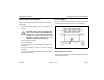
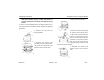
Table Of Contents
- How to Use This Manual
- Safety Signals
- Vehicle Safety
- How to Find What You Want
- A Special Word About Repairs
- Shop Manuals
- Preventive Maintenance Section
- Additional Sources of Information
- Start–Up
- Instruments and Controls
- Introduction
- Warning Lights and Buzzer
- Self Test
- Speedometer and Odometer
- Tachometer
- Coolant (Water) Temperature Gauge
- Engine Oil Pressure Gauge
- Dual Air Pressure Gauge (Air Reservoir)
- Fuel Gauge
- Voltmeter (option)
- Transmission Temperature Gauge (option)
- Air Filter Restriction Indicator (option)
- Headlight Switch
- Daytime Running Lights (option)
- Panel Lights
- ID and Clearance Lights
- Windshield Wipers/Washer
- Ignition Key Switch
- Parking Brake
- Cruise Control Switch
- Hand Throttle Control
- Heating and Air Conditioning
- Accessories
- Seats
- Steering Column and Mirrors
- Operating the Engine
- Operating the Transmission
- Using the Brake System
- Operating the Rear/Drive Axle
- More Driving Tips and Techniques
- Vehicle Recovery and Spring Brakes
- Shut–Down
- Introduction
- Maintenance Schedule and Lubrication
- Engine Maintenance
- Cooling System
- Brake System
- Air System
- Tires and Wheels
- Heater and Air Conditioner
- Electrical System
- Cab Maintenance
- Transmission and Clutch
- Steering and Driveline
- Front Axle and Suspension
- Rear Axle and Suspension
- Frame and Fifth Wheel
- Noise and Emission Control
- Consumer Information and Vehicle Identification

Operating Instructions Vehicle Recovery and Spring Brakes
Model 330 PB1318 3/01
– 111 –
with wheel chocks, chains, or other safe means to
prevent rolling before manually releasing the spring
brakes.
To move a vehicle immobilized by the spring brakes due to
loss of air pressure in the brake system, perform the following
procedure:
1. Remove the cap from the
spring chamber.
2. Remove the release stud
assembly from the side pocket,
and remove the release nut and
washer from the release stud.
3. Slide out the release stud.
4. Insert the release stud through
the opening in the spring cham-
ber where the cap was removed.
Insert it into the pressure plate.
Turn the release stud 1/4 turn
clockwise in the pressure plate.
This secures the cross pin into
the cross pin area of the pressure plate and locks it into
the manual release position.
5. Assemble the release stud
washer and nut on the release
stud.