
OPERATOR'S MANUAL


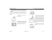
Table Of Contents
- How to Use This Manual
- Safety Signals
- Vehicle Safety
- How to Find What You Want
- A Special Word About Repairs
- Shop Manuals
- Preventive Maintenance Section
- Additional Sources of Information
- Start–Up
- Instruments and Controls
- Introduction
- Warning Lights and Buzzer
- Self Test
- Speedometer and Odometer
- Tachometer
- Coolant (Water) Temperature Gauge
- Engine Oil Pressure Gauge
- Dual Air Pressure Gauge (Air Reservoir)
- Fuel Gauge
- Voltmeter (option)
- Transmission Temperature Gauge (option)
- Air Filter Restriction Indicator (option)
- Headlight Switch
- Daytime Running Lights (option)
- Panel Lights
- ID and Clearance Lights
- Windshield Wipers/Washer
- Ignition Key Switch
- Parking Brake
- Cruise Control Switch
- Hand Throttle Control
- Heating and Air Conditioning
- Accessories
- Seats
- Steering Column and Mirrors
- Operating the Engine
- Operating the Transmission
- Using the Brake System
- Operating the Rear/Drive Axle
- More Driving Tips and Techniques
- Vehicle Recovery and Spring Brakes
- Shut–Down
- Introduction
- Maintenance Schedule and Lubrication
- Engine Maintenance
- Cooling System
- Brake System
- Air System
- Tires and Wheels
- Heater and Air Conditioner
- Electrical System
- Cab Maintenance
- Transmission and Clutch
- Steering and Driveline
- Front Axle and Suspension
- Rear Axle and Suspension
- Frame and Fifth Wheel
- Noise and Emission Control
- Consumer Information and Vehicle Identification

More Driving Tips and Techniques Operating Instructions
– 104 –
PB1318 3/01 Model 330
5. Return the control arm to the center (zero) position, then
install either the built-in alignment pin or a 1/8-inch (3
mm) dowel to ensure the control arm remains in that
position.
6. Loosen the two nuts that attach the valve to its mounting
bracket.
7. Position the valve so that the holes in the ends of the
control arm and the link rod are aligned, then connect
the ends by inserting the link bolt through them and
hand-tightening this fastener.
8. Torque the two mounting nuts to 55-75 lb. in. (6.2-8.5
N.m.).
9. Remove the alignment pin or dowel.
10. This 4-part step is only for vehicles with a dual-valve sys-
tem:
a. Detach the LH link rod from the LH valve control arm
by removing the link bolt that connects them.
WARNING! Be extremely careful when deflating
the air springs. The rear of the vehicle will drop
about 3-1/2 inches (88 mm) when the air springs
are deflated. Make sure that no persons or
objects that could be injured or damaged are
under the vehicle.
To minimize the risk of damage or injury, do not
use the dump valve to deflate the air springs.
Operate the height control valve(s) manually to
ensure positive control of air spring deflation.
b. Lower and hold the LH valve control arm 45 degrees
until air has been exhausted from the air springs
(about 30 seconds).
c. Repeat Steps 4 through 9 of this procedure with the
RH valve.
WARNING! keep away from the air springs as
they are being inflated.
d. Connect the ends of the LH link rod and valve con-
trol arm by inserting the link bolt through them. The
LH air springs should inflate to the proper height.
11. Torque the link bolt fastener(s) to 24-48 lb. in. (2.7-5.4
N.m.).
Driving with Deflated Air Springs
Vehicles with the air suspension (option): If an air spring rup-
tures, there will be enough air pressure to drive the vehicle to
a safe stop off the highway to investigate the problem.