A470 IMPACT VALIDATION PRINTER Users Guide 220117B-03 3/06 Pertech ® �
A470 Users Guide Pertech® 2006 ii
A470 Users Guide Disclaimer Information in this document is subject to change without notice. Consult your Pertech® sales representative for information that is applicable and current. Pertech reserves the right to improve products as new technology, components, software and firmware become available. No part of this document may be reproduced or transmitted in any form or by any means, electronic or mechanical, for any purpose with out the express written permission of Pertech.
A470 Users Guide Important Information to the User In order to ensure compliance with the Product Safety, FCC, and CE marking requirements, you must use the power supply, power cord, and interface cable, which were shipped with this product or which meet the following parameters: Power Supply Input power to this product must be provided by one of the following: (1) A NRTL Certified power source with a Limited Power Source. (LPS) output for use in North America, input rated 100-240 Vac, 1.
A470 Users Guide Contents Preface ...............................................................................................................vii Where to Get Additional information ......................................................... vii Chapter 1: About the Printer ..............................................................................1 Features and Options .................................................................................2 Standard Features: ................................
A470 Users Guide Chapter 4: Communication...............................................................................14 RS232 Serial Interface .............................................................................15 Serial Interface Pinout ....................................................................15 Flow Control....................................................................................16 Parallel Interface.........................................................................
A470 Users Guide Preface This manual has been written to help you install, operate and maintain your new Pertech A470 Printer. Feel free to contact us if you need further assistance after reading this manual. Please see the Troubleshooting Printer Problems section of this manual and determine the complete part number of your printer prior to calling. Pertech provides technical support Monday through Friday from 8:00 AM to 5:00 PM MST at 307856-4821.
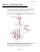
A470 Users Guide Chapter 1: About the Printer The A470 printer is a fast reliable printer designed to meet your immediate and long term needs. Industry standard RS-232 serial and 1284 compliant parallel interfaces allow for connection to any host computer or terminal system .The A470 printer features a one button configuration setup with five compatibility modes for easy integration into existing systems. When you receive your new A470 printer it will be packed in impact resistant foam packing.
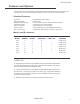
A470 Users Guide Features and Options This manual covers several models and describes features and options which do not apply to all versions. Refer to the model list below to determine which features your printer supports. Standard Features: Interfaces Memory/Firmware Resident Character Sets Dual Cash Drawer Paper Low Sensor Form In Sensor Easy Access Setup RS-232Serial, 1284 Parallel. Flash Memory. US, UK, French, German, Italian, Spanish, Hebrew Connectors for two Cash Drawers.
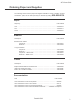
A470 Users Guide Ordering Paper and Supplies The following section lists the paper and supplies available for order. In addition to paper and ribbons, parts, service and repair may be obtained by calling 800-800-6614. Paper: Paper Ply Part Number One ............................................................................................................ 103292016 Two ............................................................................................................ 103292017 Three ........
A470 Users Guide Chapter 2: Operating the Printer This chapter describes the printer controls and provides procedures for loading Paper and Ribbons .
A470 Users Guide Paper Loading Roll paper must be 3.25 inches wide with a maximum diameter of 3.5 inches. Receipt / Journal printers can accommodate 1, 2 or 3 ply paper. Paper and other printer consumables may be purchased from Pertech by calling 1-800-800-6614. To load paper the power must be turned ON. Refer to the pictorial paper loading instructions in the lid of the printer. Specific steps may vary depending on the printer configuration. Follow the instructions on this page for model 477X printers.
A470 Users Guide 471X Paper Loading Instructions 1. Raise cover and remove the spent roll. Flip the green paper loading chute to the raised position. 2. Install the new roll so the paper exits from the bottom of the roll. 3. Insert the leading edge of the paper into the green loading chute. 4. Press and hold downward on the green paper loading button ... 5. ... Until one foot of paper exits from the mechanism 6. Flip the green paper loading chute to the lowered position. 7.
A470 Users Guide Ribbon Cartridge Replacement To replace the ribbon raise the printer cover. Leave the printer power on. Press on the Ribbon Interlock Tab and ribbon will disengage from the innerframe. Lift the old Ribbon Cartridge up and out of the printer and discard. Remove new cartridge from the plastic bag and rotate the advance tab until all slack is removed. Align the new cartridge so the exposed ribbon is between the printhead guide and the first silver roller. Lower the cartridge into place.
A470 Users Guide Validation A Validation Form can be inserted from the top or top and left once the clamp has opened. The printer will automatically clamp the form when it has been detected. Wait until the printer has finished printing and released the form prior to removal. Adjustable Features Air Gap Adjustment The air gap may need adjustment if 3 ply roll paper is used. If adjustment is required it will be evidenced by ink smudge on a Self Test printout.
A470 Users Guide Document Stop Adjustment The Document Stop limits the depth an inserted form can be placed into the Validation Slot. This defines the validation printfield height. Printers are manufactured with the maximum printfield setting of 2.16 inches but the dimension can be reduced to 1.44 inches by turning a slotted screw in the bottom of the printer case counter-clockwise (CCW). Each CCW revolution raises the document stop and decreases the printfield height 1/32” (.03125”) or .79375 mm.
A470 Users Guide Low Paper Sensor Adjustment The Low Paper Sensor is located on the inner-frame to the right side of the paper roll. This sensor is a reflective optical device that can be adjusted to accommodate various roll core diameters and quantities of paper present when low paper indication occurs. The sensor mounts on a friction bracket and can be adjusted up or down.
A470 Users Guide Maintaining The Printer There is no customer maintenance required for the A470 printer, however, you may occasionally clean lint and paper dust out of the mechanism using low pressure canned air. It is recommended that this is done on a regular basis, such as after every ribbon change. Clean the cabinet as needed to remove finger marks and dust. Use any household cleaner designed for plastics, but test it first on a small, unseen area.
A470 Users Guide Chapter 3: Print Tests and Setup Mode Two reports are available: Self Test / Configuration Report : Includes read and write tests of internal RAM; and a printed report listing the serial number, firmware, font, serial parameters, hardware settings, memory information, tallies, and the printer compatibility mode. Extended Self Test: Checks printhead pin firing, vertical line adjustment, fonts, validation clamp, pitches and character sets.
A470 Users Guide Configuring the Printer To change the configuration settings two banks of dip switches are located on the bottom of the printer. On the Self Test & Configuration Report printout you can see the dip switch configuration for both banks. Below is a table that defines what each dip switch controls. Cycle power for dip switch changes to take effect. ON = C = CLOSED OFF = O = OPEN 1 2 3 4 5 6 7 8 1 2 3 4 5 6 7 8 Dip Switch “B” Dip Switch “A” Interface Switch 19.
A470 Users Guide Chapter 4: Communication The A470 comes with two communication interfaces, RS-232 Serial or 1284 Parallel. Additionally, the printer is configured with dual cash drawer ports and a barrel type power coupling. The RS-232 interface connector is a RJ45 Female connector and requires a special cable for standard PC to printer connections. The 1284 compliant Parallel interface uses a standard DB25 Male connector.
A470 Users Guide RS232 Serial Interface The A470 printer serial interface has a RJ45 Female connector. The Baud Rate ,Parity and Flow Control are selectable through Dip Switches located on the case bottom. The settings for the port on the PC must be configured the same as the printer or communication will fail.
A470 Users Guide Flow Control The RS-232 interface uses either XON/XOFF(Software) or RTS/CTS (Hardware) protocol. This is set via dipswitch A 7. For the selected serial interface Flow Control of XON/XOFF, a particular character is sent back and forth between the host computer and the printer to regulate the communication. For RTS/CTS, changes in the RTS/CTS signal coordinate the information flow. Parallel Interface The Parallel interface is compatible with IEEE 1284 Parallel Interface Standards.
A470 Users Guide Cash Drawer Each cash drawer driver will source 24 volts for 75 ms to the “solenoid +” pin of the appropriate RJ-11 jack when the proper cash drawer command is executed. The cash drawer command must be preceded by a line terminator. The command for the cash drawer may vary for the Compatibility Mode selected.
A470 Users Guide Chapter 5: Trouble Shooting Printer Problems Trouble Shooting General Issues Following are symptoms your printer may exhibit and simple solutions the printer operator could implement. • Printer failed to print after the roll paper was replaced. The top cover must be closed for the printer to print. • The power switch is turned ON but the printer is dead. The Green Power LED is Off. Make sure the outlet has power and the power cord is plugged into the back of the printer.
A470 Users Guide • Receipt does not come all the way out. Printer is jammed. To remove paper that has jammed, it is advisable to: 1) Tear off any paper that fed out of the top of the mechanism 2) Press downward on the metal release bracket 3) While pulling the remaining paper out of the mechanism backwards • Status light is Red (not Green) and printer will not respond. Remove the ribbon cartridge and paper roll. Using Low Pressure Canned Air spray out the areas around the three sensors.
A470 Users Guide Trouble Shooting Other Issues Fault Mode The printer will enter a Fault Mode and will not operate when certain failure conditions are encountered. Confirmation of this condition can be accomplished by the host on the DTR (pin 8) or status with an RS-232 interface, or on the printer fault line (pin 15) for the parallel interface.
A470 Users Guide Getting Service and Technical Support Service You can rely on Pertech for fast turnaround, flexibility, and a highly trained and dedicated staff to return your equipment back in first class working order. As part of Pertech, we are very familiar with all Pertech printers.
A470 Users Guide Appendix A:Pitch / Characters Per Line The printer has 14 PITCH / FONT combinations. These are developed from 4 basic character fonts (2 normal and 2 double wide) and a variable intercharacter space. Chars Chars Line Method / Inch / Line Length Dot Columns Dots Ch+Sp=To / Line 6.0 16 2.67 15+09=24 384 6.6 18 2.75 15+07=22 396 7.2 20 2.78 15+05=20 400 8.0 22 2.75 15+03=18 396 9.0 25 2.
A470 Users Guide DOTS / LINE dots per line - number of dot columns used within the 400 dot printfield - a product of dot columns (To) and CHARS / LINE The normal fonts are 5 or 7 dot columns wide (Ch) and the Double Wide fonts are 11 or 15 dot columns wide (2x + 1). No single dot can fire on adjacent columns, i.e. a font which is 7 dot columns wide will not activate any single dot more than 4 times (positions 1, 3, 5 & 7). The printfield is 2.78” wide and has 400 dot columns, each .
A470 Users Guide Appendix B: Specifications Some features listed in this specification do not apply to all products in the Pertech A470 series. Refer to Chapter 1: Features and Options of this manual to determine which features apply to a particular model. Operating Print Speed................................................... 4 Lines Per Second Paper Feed Speed ....................................... 3.47 Inches Per Second Validation ......................................................
A470 Users Guide Electrical Interfaces...................................................... RS-232 And Parallel Baud Rates................................................... 300 To 19200 Buffer ............................................................ 7 K RS-232 Connector........................................ RJ45 Female Parallel Connector ........................................ DB25 Male Cash Drawer Drivers .................................... 2 With Sense Cash Drawer Connectors ...................
A470 Users Guide Pertech® 2006 26
A470 Users Guide Index A I Adjustable Features 8, 18 Advanced Control Language vii Air Gap Adjustment 8, 18 Incorrect rom checksum 20 Independent feed 2 Information to the User iii Interfaces 2, 25 Interface Cable 16, iv B Baud 15, 25 J C Jam.
A470 Users Guide R T Ram test failure 20 Resident character sets 2 Revision 21 Ribbon Cartridge 7, 19 Ribbon Interlock Tab 7 Roll Diameter 24 Roll Paper Plies 24 Roll Paper Width 24 Technical Support 21 Trademarks iii Trouble Shooting 18, 20 S Validation Form 8 validation printfield height 9 U USB 1, 14, 16, 25 V Sector Gear 9 Self Test 8, 9, 12 Serial Number 21 serial number 12 Service 21 service 3, 11, 21 Slow Down mode 4 Specifications 22, 24 Standard Features 2 Status light 18, 19 W Warning 14
A470 Users Guide Warranty Warranty Pertech Resources warrants all of its transaction printers against defects in material and workmanship for a period of 24 months from date of shipment by Pertech Resources or the rated maximum number of transactions for the specific product – whichever comes first. Kiosk printers, mechanisms and distributed products carry warranties specific to their application or manufacturers’ warranty. Contact warranty@pertechresources.com for details on the specific product warranty.