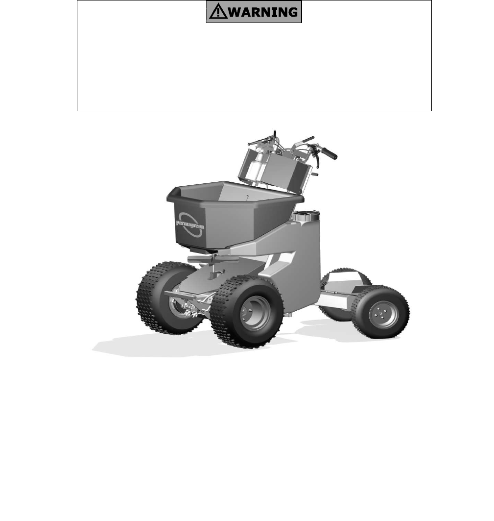
PermaGreenTM Triumph Spreader Sprayer Operator’s Manual To Avoid serious injury or death: This Triumph MUST pass a New Machine Pre-Operation Inspection prior to use. • DO NOT start the machine until instructed do so during the Pre-Operation Inspection. Read this Manual before using. ALL operators and mechanics MUST be trained.
RECORD OF REVISIONS i Keep this record in the front of the manual. When a revision is provided, insert the revised pages in the manual. Record the revision number, the date the revision was inserted in the manual, and provide your initials or signature in the BY column.
ii TABLE OF CONTENTS Section Page 1. Introduction to using Your Manual. .............................................................................................. 1 2. New Machine Pre-operation Inspection ................................................................................ 2-3 3. Safety Manual........................................................................................................................ 5-13 a) Machine Safety Labels...............................................
iii Page left intentionally blank
Special Messages Introduction to Using Your Manual Congratulations on the purchase of your new Triumph A1A Sprayer Spreader. Before attempting to start or operate your Triumph, please read the Operator Manual and safety labels on the machine. Follow all the instructions carefully. This manual explains machine inspection, operation, troubleshooting, and service, as well as, the safety features of the machine.
New Machine Pre-Operation Inspection Pre-Operation Inspection 2 ♦ When the Drop Handle Lever is pushed backwards, the entire Handle bar assembly will pivot up or down and shall automatically latch when placed in either position. ♦ Component Inspection. Avoid serious injury! This Triumph MUST pass a Pre-Operation inspection prior to use. • DO NOT start the machine until instructed to do so. • Do not operate unless all Safety Devices are functioning properly.
New Machine Pre-Operation Inspection ♦ Drive and Brake Systems Inspection. ♦ Steering System Inspection ♦ Remove the chock blocks and unlock both Brake Levers. ♦ With the machine fully loaded, drive through a series of lock to lock figure eights for 5 minutes. The steering effort to come out of the tightest turn shall be less than 30 pounds of force. ♦ On a paved parking lot, shift into Low Gear and pull the Throttle Lever. The machine should smoothly accelerate to about 3.5 mph.
4 Page left intentionally blank
5 Safety Manual ALL USERS AND OWNERS SHALL READ AND UNDERSTAND THIS SAFETY MANUAL BEFORE OPERATING THE TRIUMPH. LACK OF TRAINING, OPERATOR ERROR OR CARELESSNESS MAY CAUSE SERIOUS INJURY OR DEATH TO THE OPERATOR OR OTHERS. Understanding Safety Messages Machine Labels This manual and the labels on the machine contain messages to bring to your attention to potential safety concerns, machine damage, operation, and maintenance information.
SAFETY MANUAL 6 FIGURE 3, Panel Labels FIGURE 2, Rear Labels Machine WARNING Labels (Refer to FIGURE 2) K) WARNING (DUPLICATE LABEL ON FRONT HOOD) Exposed moving parts can cause severe injury. DO NOT start engine or operate machine without guards in place. L) WARNING PINCH POINT! Keep hands and feet away M) WARNING AVOID SLIPPING INJURY. Stand only on footpads; Replace worn footpads; Keep footpads clean. N) WARNING AVOID TRIPPING INJURY. Keep a firm grip on both handles. Drop handlebars if necessary.
Safety Manual 7 UNDER HOOD If you can read this sign, a guard has been removed. DO NOT operate with guard removed. UNDER REAR BELT GUARD If you can read this sign, a guard has been removed. DO NOT operate with guard removed. FIGURE 4, Side Labels Machine WARNING Labels (Refer to FIGURE 4) T) WARNING Do Not operate on slopes over 15 degrees. You instinctively stand at your balance point (BP). When your BP is outside the BALANCE ZONE, the slope is over 15⁰. *Illustrations show operator on 15⁰ slopes.
Safety Manual 1 8 3 Minimum Operator Qualifications Owner’s Responsibility To avoid injury: The owner is responsible for training himself and all other operators and mechanics. Before starting the engine and/ or operating the machine, each operator must read and understand the Operator Manual, the Safety Manual and all other training material. If the person cannot read English, the owner is responsible to explain the material to them.
Safety Manual 6 9 7 Inspecting work area Operation Avoid serious injury! • DO NOT change the engine governor setting or over speed the engine. The top engine speed when the machine is in Neutral is 3450 RPM. Use the electronic multifunction display to monitor the top speed and make adjustments as necessary. Prior to operating, carefully inspect the work areas for hazards or uneven ground that may be hidden in the grass.
Safety Manual 10 12 9 Inspect machine before each use Forward operation Examine the machine prior to each use. DO NOT use the machine if any parts are not in good working condition. • Check for worn tires, cracks in parts, loose or missing bolts, cotter pins etc. and replace or repair before operating. Loss-of-control may cause death or serious injury.
Safety Manual 15 To avoid Loss-of-control, tip-over, and rollover Loss-of-control, tip-over or rollover may cause death or serious injury. This machine has a high center of gravity and turf conditions affect stability. Slopes are a major factor in loss-of-control, tip-over, and rollover accidents. • Never shift gears while the machine is moving as this may cause a rapid slowdown or stop the front wheels causing loss-of -control or a forward tip over.
Safety Manual When pointing across an incline… (continued) Recommendations for driving across a hillside: • Lean uphill to provide better balance for you and transfer more weight to the uphill wheels. • DO NOT change speed suddenly. • DO NOT make sharp turns as you may lose your balance and be thrown off the machine or loose control. When making turns, slow down and make gradual turns. The machine also has a tendency to rollover when performing this maneuver.
Pre-Operation Inspection 18 13 20 Tire Safety Pesticide Safety Tires are filled with pressurized diluted RV antifreeze to provide ballast for a lower center of gravity. Explosive separation of rim and tires may cause serious injury. The improper use, handling, application, and disposal of pesticide products applied by this machine may cause death or serious injury. • DO NOT remove fluid from tires. • All replacement tires must be fluid filled.
Driver’s Training and Operation 14 DO NOT attempt to start or operate this machine until you have read and are thoroughly familiar with this Operator’s Manual. Read it now before beginning. All operators and mechanics must be trained before operating this machine! Supervised Driver’s Training Locate, identify, and explain the function of the following (refer to FIGURE 5 For location): Before beginning training: • Machine Safety Labels: Safety Device = (SD).
Driver’s Training and Operation Machine controls Locate, identify and explain the function of the following: (refer to Fig. 6 M. The Shift Lever selects a gear on the Transaxle. There are 4 gears available: Reverse, Neutral, Low, and High. A Stop locates Neutral. Low Gear provides a forward speed of 3.5 MPH and is used on hills, in small areas where detailed trimming is required, and when the Triumph is operated as a walk-behind unit. High gear provides a forward speed of 5.0 MPH. N.
Driver’s Training and Operation Demonstrate and instruct the trainee on the following topics: Read Machine Safety Label WARNINGS including: A, To avoid injury preview work area; Q, Improper Operation and improper maintenance; L, Pinch point; and K, Exposed Moving parts can cause severe injury before starting or operating the Triumph.
Driver’s Training and Operation PHASE II: Driving the machine in High Gear. 17 Phase VII: Backing Up. Repeat Phase I training using High Gear. Read Safety Manual WARNING 13, Reverse operation now PHASE III: Driving with a load. • Repeat Low and High Gear Training outlined in Phase I and Phase II with a partially filled Hopper and Tanks • Gradually increase the weight as the trainee demonstrates his ability to control the machine with the increased weight.
Driver’s Training and Operation • Shift into Low Gear and repeat the previous test. Confirm that the engine does not start in gear. Phase IX: Loading and unloading the machine on a Transport. Read Safety Manual WARNING 16, Transporting before attempting to load or unload the Triumph from a transport. 18 3. Brake Systems A Front Brake System. Trainee must be instructed how to safely load and unload the Triumph from a transporting vehicle.
Driver’s Training and Operation • Shift into High Gear and drive straight forward.. Confirm that the machine travels in a straight line without pulling right or left and no unusual noise is detected. • Shift into High Gear and maneuver through a series of lockto-lock figure eights.
20 Page left intentionally blank
Spreader Operation 20 21 FIGURE 10 Pesticide Safety The improper use, handling, application, and disposal of pesticide products applied by this machine may cause death or serious injury. • Read and follow product label and Material Safety Data Sheet (MSDS) precautions for handling, mixing, applying, and disposing of pesticides applied by this machine. Some materials may present health hazards that will require the use of Personal Protection Equipment (PPE). Always wear required PPE.
Spreader Operation • Make the edging pass keeping the right side of the granular spread pattern inside the edge of the sidewalk, ornamental beds, etc. • When it is necessary to stop the machine, simultaneously release the Throttle Lever and pull the Hopper Lever to the rear to stop the flow of granular material.
Spreader Operation • Using the Third-hole Lever, position the Third-hole Adjustment Plate against the Calibration Gage and position the Memory-Lock until it pops into the Lever and locks its position. • Remove the Calibration Gage. • Close and open the Third-hole several times and verify the Third-hole setting is 13. Readjust as necessary. • Record both the Calibration Gage setting and the MemoryLock setting for future use. NOTE: The correct Calibration Gage setting must be verified from time to time.
24 Page left intentionally blank
Sprayer Operation 20 25 (H) with lock is mounted on the left handle which allows the operator to spot spray the liquid product while blanket covering the area with granular product. Pesticide Safety The improper use, handling, application, and disposal of pesticide products applied by this machine may cause death or serious injury.
Sprayer Operation 26 being treated. The sprayer and spreader can be operated at the same time to provide even and complete distribution of both the sprayed and spread products to the entire area. Sprayer Operating Controls • To select which nozzle will spray, point the Spray Control Valve handle for the gear selected to the desired nozzle either Broadcast or Trim. The front Spray Selector Valve (I) is used for High Gear and the rear Spray selector Valve (J) for Low Gear.
Sprayer Operation and Calibration • Rotate the nozzle body on the pipe nipple so that the spray pattern is pointed slightly forward. • Adjust the spray nozzle body so that the pattern width, measured from outermost droplets to outermost droplets, is 6 feet (3.6 meters). Increase the pattern width by raising the nozzle level. Decrease the pattern width by lowering the nozzle level. • Repeat the procedure for the Low Gear Trim Nozzle (XR10008VP-color coded yellow).
Sprayer Operation and Calibration Applying the Spray. Plan the spray application pattern required to cover the manual application area. MPORTANT: Use caution when spraying near desirable vegetation or painted surfaces to avoid damage. IMPORTANT: Use caution when spraying in windy conditions to avoid damage. • To spray, invert the spray bottle and squeeze the bottle with enough pressure to create the spray pattern needed. • To stop spraying, stop squeezing and right the bottle. Filling the Spot Sprayer.
Troubleshooting Manual If you are experiencing a problem that is not on the list or are having difficulty, check with your PermaGreen Dealer or contact PermaGreen Tech Support at 800-346-2001 or tech@permagreen.com.
Troubleshooting Manual If you are experiencing a problem that is not on the list or are having difficulty, check with your PermaGreen Dealer or contact PermaGreen Tech Support at 800-346-2001 or tech@permagreen.com.
Troubleshooting Manual If you are experiencing a problem that is not on the list or are having difficulty, check with your PermaGreen Dealer or contact PermaGreen Tech Support at 800-346-2001 or tech@permagreen.com.
32 Page left intentionally blank
Service Manual Service WARNING An untrained operator or mechanic can cause an accident with serious injury to himself or bystanders. Read Safety Manual WARNING 2, Supervised Driver’s Training and machine safety label Q, Improper operation and maintenance before starting, operating, repairing or performing maintenance on the Triumph. Read Safety Manual WARNING 19, Maintenance and service before starting, operating, repairing or performing maintenance on the Triumph.
Service Manual □ Check tightness of Articulating Joint Bolts □ Test Safety Devices □ Check drive belt and spinner/clutch belts, replace if necessary □ Flush and clean Spray tanks □ Run RV anti-freeze or Windshield washer solution through spray system □ Calibrate Spray System □ Calibrate Spreader System 34
Service Manual 19 35 Read Safety Manual WARNING 21 Handling and Disposal of hazardous waste products before starting or operating the Triumph. Maintenance and service Changing engine oil (Refer to FIGURE 20) Improper maintenance can cause serious injury. Drain the used oil when engine is warm. Warm oil drains quickly and completely. • Clean around Dipstick and oil drain plug. • On a level surface, place the machine in a maximum left turn and Lock both Brakes.
Service Manual Oil VolumeEngine Oil VolumeClutch SAE 30 0.63 quart (0.6 liter) 0.53 US quart (0.5 liter) +50ºF (10° C) and higher SAE 10W -30 0.63 quart (0.6 liter) 0.53 US quart (0.5 liter) +30ºF to 22ºF (0°C to -30°C) SAE 0.63 quart (0.6 liter) 0.53 US quart (0.5 liter) Temperature Range Oil Type +50ºF (10° C) and higher 5W-30 36 Adjusting engine speed to 3450 RPM Engine speed is part of the Operator Presence Control/ Throttle/Clutch Safety Device. Keep the top speed at 3450 RPM.
Service Manual 37 Brake adjustment (Refer to FIGURE 25) To increase braking, loosen jam nut and extend Turnbuckle Adjuster. Test braking and adjust as necessary. Tighten jam nut. To decrease braking, loosen jam nut and retract Turnbuckle Adjuster. Test braking and adjust as necessary. Tighten jam nut. After adjusting, Conduct the Safety Device Test 3, Brake Systems, (page 18) in the “Driver’s Training and Operation” section of this Manual.
Plumbing and Electric Schematics FIGURE 25, Plumbing Diagram FIGURE 26, Wiring Diagram A) B) C) D) E) F) G) H) I) J) K) L) M) N) O) P) Q) R) S) T) A) B) C) D) E) HIGH gear BROADCAST nozzle HIGH gear TRIM nozzle LOW gear BROADCAST nozzle LOW gear TRIM nozzle Nozzle body, cap and gasket, and strainer Nozzle body, cap and gasket, and strainer Nozzle body, cap and gasket, and strainer Nozzle body, cap and gasket, and strainer Spray selector valve, HIGH gear Spray selector valve, LOW gear Spray control valv
Specifications Engine : Honda™ GX200RH2 Clutch: Centrifugal Honda™ wet clutch with 2:1 reduction Transmission: Tecumseh 855-001C (reverse, neutral and 2 forward gears) Pump: Flo-jet™ 2GPM belt-driven diaphragm pump Front tires: 9.50” - 18” x 8” Kenda Scorpion traction tires Rear tires: 6.50” - 13” x 6” Kenda turf tires Hopper: 150 lb capacity Tanks: Twin 6-gal tanks treats 48,000 ft @32 oz./ft² or 24,000 ft @64oz./ft²) Speed: 5.0 mph (high gear) 3.5mph (low gear) Fuel tank: 0.
Warranty WARRANTY Perma-Green Supreme, Inc. hereby warrants to the original purchaser that the Triumph A1A manufactured by PermaGreen Supreme, Inc. will be free from defects in material and workmanship for a period of one year from the date of delivery, except as noted below. PROTECTION PLAN The Company will provide replacement parts for parts found by the Company to be defective. Such replacement parts will be provided free of charge to the original purchaser for one year from the date of delivery.
41 Page left intentionally blank