P E R MA P U R E INSTRUCTION MANUAL CLASSIC THERMO-ELECTRIC COOLERS Model M225 Version 4.07 Perma Pure LLC 8 Executive Dr, PO Box 2105 Toms River, NJ 08754 www.permapure.com Tel: 732-244-0010 Tel: 800-337-3762 (toll free US) Fax: 732-244-8140 Email: info@permapure.
TABLE OF CONTENTS A: Specifications................................................................................................................ 3 B: Limited Warranty........................................................... Error! Bookmark not defined. C: Principle of Operation ................................................................................................... 5 D: Installation ..............................................................................................................
A: SPECIFICATIONS Physical Description Single (Series) / Dual (Parallel) Channel System 2 x 5” Heat Exchangers connected in series or parallel 2 Active (cooled to 4°C) Heat Exchangers LCD temperature display (optional) Operating Specifications Sample Gas Flow Range 3-5 LPM 6.5-10.8 SCFH Inlet Dew Point at Rated Flow Maximum Cooling Rate 140°F @ 20% H2O, 5 LPM 60°C 112 BTU/Hr 118kJ/Hr Dimensions 11.20 x 7.25 x 11.20 in. HWD 28.5 x 18.4 x 28.5 cm Weight 17 lbs 7.
B: LIMITED WARRANTY Perma Pure LLC WARRANTY and DISCLAIMERS Perma Pure (Seller) warrants that product supplied hereunder shall, at the time of delivery to Buyer, conform to the published specifications of Seller and be free from defects in material and workmanship under normal use and service.
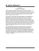
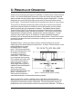
C: PRINCIPLE OF OPERATION Thank you for purchasing the Perma Pure Baldwin™ Classic Series Thermo-Electric Cooler. Our Classic Model M225 features a unique slim design leaving additional space to install or access other sample conditioning system components. A unique drop-down door on the M225 provides easy access to electronic boards and the power supply. The electronic control board is mounted on the door for easy access.
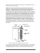
transferred to the hot side of the Peltier element where it is dissipated into the heat sink and surrounding environment. Baldwin-Series Classic Thermo-Electric Coolers remove the moisture from the sample gas by cooling the gas as it passes through a laminar impinger (heat exchanger). A diagram showing the gas flow path through an impinger is shown in the Appendix.
condenses, the condensate exits the heat exchanger through the bottom drain connection. Particulate matter passing through the sample cooler is removed by an optional Perma Pure pre-filter, located downstream from the cooler along with an optional water slip sensor. The conditioned sample gas can then be directed to the gas analyzers.
D: INSTALLATION The Model M225 should be installed away from heat sources in a well ventilated area of an instrument rack or enclosure. The more stable the ambient temperature environment around the Model M225, the better the output dew point stability. Sample tubing connections to the Model M225 depend on the heat exchanger material of construction. A cooler with a stainless steel heat exchanger uses a stainless steel inlet fitting.
E: START-UP PROCEDURE Plug in the power cord to a properly grounded main circuit. The Ready Green LED will come on within 3 minutes, indicating the relay temperature (10°C) has been achieved. After approximately 3 minutes, the set point of +5°C. (41°F) is achieved. The sample gas flow may be started immediately after the READY Green LED comes on. The Model M225 is virtually maintenance free. However, in the event of electrical problems, refer to the troubleshooting guide in this manual.
F: LED INDICATORS The Model M225 has four green and two red LED operating indicators. These indicators are arranged vertically on the front of the cooler with the right side corresponding to CH1 and the left to CH2. The bottom green LED’s indicate the READY operating temperature status, normally set for 10°C (50°F). After the setpoint temperature is reached, the sample pump may be turned on by other devices. When the impinger temperature is below 10°C (50°F) the ready LED’s will be on.
G: I/O TERMINAL BLOCK DESCRIPTION The I/O terminal blocks are found on the bottom panel of the cooler: TB1 TB1 is the standard analog output (low voltage DC output) for all Classic Series Thermo-Electric Coolers. Model M225 has two active 5” heat exchangers. The output is 0vdc to 2.5vdc for a temperature range of 0°C to 25°C. C Terminal 1 is earth ground. This terminal should be used to ground the shield of the shielded twisted pair cable that is used to connect the analog output to a receiving instrument.
H: TEST & ADJUSTMENT PROCEDURES NOTE: All test and adjustment procedures have been performed at the factory. Therefore, no adjustment should be necessary. A. Main Control board (1) WARNING: Before connecting power to the cooler, be aware of the HAZARDOUS LIVE VOLTAGE on the control board. Disconnect power from the cooler before opening the swing-down "L-door". Note: The auxiliary output board must be removed if the cooler is so equipped. Remove the thermocouples from TB1 and TB2.
B. Display Board (not standard on the Model M225) (1) WARNING: Before connecting power to the cooler, be aware of the HAZARDOUS LIVE VOLTAGE on the control board. Disconnect power from the cooler before opening the swing-down "L-door". Remove display cover from the front of the swing-down "L-door". Connect a voltmeter between the ground test point, TP7 on the main control board and TP1 on the display board, the red lead to TP1 and the black lead to TP7.
For Current Output (3a) If the auxiliary analog output board is set up for current output, set the ammeter to 200ma range. Connect the ammeter to TB1 (the channel 1 current output terminal), the black lead to the negative (-) terminal and the red lead to the positive (+) terminal. (4a) Adjust POT4 (the zero pot) to obtain a 4mA reading on the ammeter. (5a) Set the thermocouple generator to 25°C. (6a) Adjust POT1 (the span pot) to obtain a 20mA reading on the ammeter.
I: DESCRIPTION OF OPTIONS Baldwin™-Series Classic Series Thermo-Electric Coolers have three available options: (1) temperature display; (2) alarm relay/water slip, and (3) auxiliary analog output. Classic Series Coolers may be equipped with any one or all of the options. All external I/O connections for these options are available through the terminal blocks on the bottom of the cooler. 1. Display Option The display option is a secondary board that is mounted on the main control board.
J: “NEW JERSEY” THERMOCOUPLE OPTION Some air quality management districts (e.g., those in New Jersey and Southern California) require temperature measurement of the gas stream at the outlet of the last heat exchanger on the cooler. Baldwin offers a 1/32-inch diameter hypodermicstyle type K thermocouple that can be inserted into a special heat exchanger (i.e., it has a small port for insertion of the thermocouple) so the actual sample dew point temperature can be measured.
K: TROUBLESHOOTING Symptom No LED(s) and no fan. Check AC power input. No LED(s) and fan on. AC input fuse on control board. DC output fuse on control board. VC on control board. Action Ensure that AC power is connected. Replace fuse as necessary. Replace fuse as necessary. Replace control board. LED(s) on and no fan. AC input fuse on power supply. +12vdc TB4 on control board. Replace fuse as necessary. Replace power supply. Impinger remains at ambient temperature. Thermocouple failure LED is on.
For further service assistance, contact: Perma Pure LLC P.O. Box 2105 8 Executive Drive (08755) Toms River, NJ 08754 Tel: 800-337-3762 (toll free U.S.) Tel: 732-244-0010 Fax: 732-244-8140 Email: info@permapure.
L: SPARE PARTS Classic Model M225 Part No.
Model CD2 (Models 4S-M225-9ACD2, 4S-M225-9DCD2) Part No.
APPENDIX A: CLASSIC MODEL M225 21
Modular Series Thermo-Electric Coolers Control Board
A B C D TB2 1 2 3 100 R4 C4 CHN1_READY TC_1_OK WATER_SLIP2 WATER_SLIP1 CHN2_READY TC_2_OK C6 .1uf 1 2 3 4 5 6 7 15uf 3 2 1 C7 15uf 1 3 6 2 4 11 8 12 10 VCC C18 .1uf C23 .1uf C24 .01uf 1 2 3 C13 .01uf VCC C14 .1uf YEL RED TB1 Channel 1 P1 C2 15uf + + C5 .1uf LM556C CON TRG THRES RST U4B LM556C CON TRG THRES RST U4A 100 R3 C3 C8 .1uf C1 .1uf 1 2 3 4 5 6 7 9 13 NOTE 5 5 1 .
A B C D 2 1 1 2 3 4 5 6 7 8 VCC VCC CHN1_READY TC_1_OK WATER_SLIP2 WATER_SLIP1 CHN2_READY TC_2_OK VCC VCC 1 1 1 1 100K RN1D 100K RN1C VCC 100K RN1B 100K RN1A 5 4 3 2 1 2 NOTE 1: For single sample streams only, if separate water slip and temperature alarms are required, jumper pins 1 & 2 on JP1, JP2 and JP3. For dual sample streams, jumper pins 3 & 4 on JP1, JP2 and JP3. Water Slip 1 TB5 2 1 P1 Water Slip 2 TB2 C8 .1uf C3 .1uf C7 .1uf C6 .001uf C4 .1uf C5 .
APPENDIX B: SAMPLE CONDITIONING SYSTEM 22
AIR DIMENSIONS INCORPORATED 1371 West Newport Center Dr., Suite 101, Deerfield Beach, FL 33442 - Phone 954-428-7333 or 800-423-6464 Fax 954-360-0987 http://www.airdimensions.com e-mail address -Info@AirDimensions.com MINI DIA-VAC® MAINTENANCE AND DISASSEMBLY INSTRUCTIONS A. General Operations Characteristics 1. Normal motor coil temperatures may be 160 - 180 degrees F. Winding insulation is Class B. Please note the two fans are different, so before removing the fans, note which side they belong on. 2.
*Diaphragms require close precision tolerance, therefore only ADI diaphragms should be used as replacements. C. Disassembly of Head Section and Service Diaphragm 1. Remove head section by unscrewing the four large bolts. A flat-bladed screw driver may be needed to gently pry the head free of the service diaphragm. **If you have Teflon coating on the heads use caution not to scratch the surface. 2.
E. Related Torque Values 1. Head bolts - 110 inch pounds. 2. Valve body screws and Diaphragm plate screws - 70 inch pounds Dia-Vac® is a Registered Trademark of Air Dimensions Inc.
1. Single Pump Head Loading Note: Use only MASTERFLEX Precision Tubing with MASTERFLEX Pumps to insure optimum performance. Use of other tubing may void applicable warranties. Contents: One pump head, one 15 in (38 cm) length of silicone tubing, one mounting hardware package, manual and tubing loading key. Supplied tubing loading key required for assembly. a) Separate the end bells (the pump head halves). Hold the end bell containing the rotor as shown with the tubing retainer grooves facing down.
Set contains four #8-32 screws, four washers, and four wingnuts. Number of heads To be mounted 1 2 3 4 Cold- rolled steel Order number MN-07013-02 MN-07013-03 MN-07013-03 MN-07013-07 Stainless steel Order number MN-07013-04 MN-07013-05 MN-07013-08 MN-07013-09 2. Multi-Channel Mounting Flat bladed screwdriver required for mounting. Tubing loading key required for mounting. Note: Other special mounting hardware for multi-channel pumping. See “ 3. Replacement Parts and Accessories”.
CHART OF VOLUME PERCENT WATER CONCENTRATIONS AT SATURATION FOR VARIOUS TEMPERATURES AT STANDARD PRESSURE (ATMOSPHERIC PRESSURE) DEGREES C DEGREES F VOLUME % DEGREES C DEGREES F VOLUME % +100 + 212 100.00 +2 + 36 0.696 + 90 + 194 69.20 +1 + 34 0.649 + 80 + 176 46.70 0 + 32 0.602 + 75 + 167 38.70 -1 + 30 0.555 + 70 + 158 30.70 -2 + 28 0.510 + 65 + 149 25.20 -3 + 27 0.469 + 60 + 140 19.70 -4 + 25 0.431 + 55 + 131 15.50 -5 + 23 0.396 + 50 + 122 12.20 -6 + 21 0.363 + 45 + 113 9.45 -7 + 19 0.333 + 40 + 104 7.
MOISTURE CONVERSION TABLE DEWPOINT F C -110 -108 -106 -104 -102 -100 -98 -96 -94 -92 -90 -88 -86 -84 -82 -80 -78 -76 -74 -72 -70 -68 -66 -64 -62 -60 -58 -56 -54 -52 -50 -48 -46 -44 -42 -40 -38 -36 -34 -32 -30 -28 -26 -24 -22 -20 -18 -16 -14 -12 -10 -8 -6 -4 -2 0 +2 +4 +6 +8 +10 +12 +14 +16 +18 +20 +22 +24 +26 +28 -166 -162 -159 -155 -152 -148 -144 -141 -137 -134 -130 -126 -123 -119 -116 -112 -108 -105 -101 -98 -94 -90 -87 -83 -80 -76 -72 -69 -65 -62 -58 -54 -51 -47 -44 -40 -36 -33 -29 -26 -22 -18 -15 -1