Luxury Operation & Installation Manual Signature Series (HP15-, HP24- and HP48-inch models) Beer Dispenser Models Only HP15TS HP24TS HP48RT Form No. Z2259 Rev.
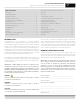
Operation & Installation Manual Signature Series Beer Dispensers (HP15, HP24 and HP48 models) Table of Contents Introduction........................................................................................................... 3 Warranty Registration...................................................................................... 3 General Precautions.......................................................................................... 4 Installation Specifications............................
Operation & Installation Manual Signature Series Beer Dispensers (HP15, HP24 and HP48 models) GENERAL PRECAUTIONS DANGER Risk of child entrapment, before you throw away your old refrigerator or freezer, take off the doors and leave shelves in place so that children may not easily climb inside. DANGER Altering, cutting of the power cord, or removal of the power cord, removal of power plug, or direct wiring can cause serious injury, fire and/or loss of property and/or life and will void the warranty.
Operation & Installation Manual Signature Series Beer Dispensers (HP15, HP24 and HP48 models) HP15TS Model (Figure 1) 50" Area in which electrical outlet must be located Power cord 65/8" off floor.* 1 5 16" Signature Series HP15 Models Tapping 7 7 8 16" 7 16" * Leg leveler can add 3/4" to these dimensions when fully extended. 7 25 16" Values may change due to custom pull with a wood overlay door. 24" (with 1/16" toleramce) 15 15 16" Min. clearance for door swing.
Operation & Installation Manual Signature Series Beer Dispensers (HP15, HP24 and HP48 models) HP24TS Model (Figure 2) 50" Area in which electrical outlet must be located 9 Signature Series HP24 Models Tapping Power cord 65/8" off floor. * 7 16" 15 7 8 16" 11 16" * Leg levelers can add 1 1 4" Min. clearance from a corner to acheive 90 door swing. 3/4" to these dimensions when fully extended. 7 25 16" Value may change due to custom pull with a wood overlay door. 15 24 16" Min.
Operation & Installation Manual Signature Series Beer Dispensers (HP15, HP24 and HP48 models) HP48RT Models Signature Series HP48 Models 50" Area in which electrical outlet must be located. Door (Figure 3)/Drawer Models (Figure 4) 12 1/4" Power cord 81/4" off floor.* 11 15/16" 1 1/4" Min. clearance from a corner to acheive 90 door swing. 25 7/16" Values may change due to custom pull with a wood overlay door. 8 7/16" * Leg leveler can add 3/4" to these dimensions when fully extended.
Operation & Installation Manual Signature Series Beer Dispensers (HP15, HP24 and HP48 models) PREPARING THE SPACE Make sure that the space that the opening where the Perlick cabinet(s) is/are to be installed is properly prepared. Refer to Figure 1 (page 5), Figure 2 (page 6) and Figure 3 (page 7) to ensure proper space dimensions and electrical service are correct for the model to be installed.
Operation & Installation Manual Signature Series Beer Dispensers (HP15, HP24 and HP48 models) ANTI-TIP BRACKETS WARNING Unit may tip forward if loaded racks/shelves are all pulled out at the same time. To prevent tipping and provide a stable installation, the unit must be secured in place with the anti-tip brackets provided with the unit.
Operation & Installation Manual Signature Series Beer Dispensers (HP15, HP24 and HP48 models) INSTALLATION Figure 8 - Leveling CAUTION Finished flooring should be protected with the appropriate material to avoid damage from moving the unit. If unit has been laid on its back or sides, place unit upright and allow minimum of 24 hours before connecting power. 1. Plug in the unit into the 15 amp grounded outlet located in the installation opening.
Operation & Installation Manual Signature Series Beer Dispensers (HP15, HP24 and HP48 models) TOE PLATE INSTALLATION SHELVING When the unit is secured in place, install the louvered toe plate. Secure louvered toe plate by snapping the latch into the latch catch on the unit. Refer to Figure 9 (below) for Toe Plate Installation Illustration and Figures 10 (page 12) and 11 (page 13) for Toe Plate Wood Overlay template.
SW 7/8" 7/64" 9/32" 1/4" 1/2" 1/8" 7/64" 9/32" 3/32" 1/32" THICK (20GA) GALVANIZED OR STAINLESS STEEL RECOMMENDED REAR VIEW R1/4" 7 1/16" C 1 29/32" 17/64" 4 1/8" SECTION B-B SCALE 1 : 2 9/32" 1/32" 3/8" 2 7/64" 5/32" 29/64" 1/4" TYPICAL 1" DETAIL D SCALE 1 : 1 11/16" 3/8" DETAIL C SCALE 1 : 2 3" TYPICAL 3/32" 1" 5/16" TYPICAL CHECKED DRAWN FINISH: QTY.: 4/23/2008 4/23/2008 NAH DATE 4/23/2008 NAH SIGNATURES DESIGNED PURCHASE REC.
SW 11 9/16" B B C 7/8" 7/64" 9/32" 1/4" 1/2" 1/8" 7/64" 9/32" 3/32" 1/32" THICK (20GA) GALVANIZED OR STAINLESS STEEL RECOMMENDED 2 METAL CLIP REQUIRED FOR SNAP IN RETAINER THAT ASSEMBLES GRILL TO THE UNIT. THIS CLIP MUST BE SCREWED TO THE GRILL USING THE FEATURES SHOWN IN DETAIL VIEW "D" 5/32" 43/64" 29/64" 7/32" 1" 3/32" 3/8" 11/16" 3/8" DETAIL C SCALE 1 : 2 1" DETAIL D SCALE 1 : 1 5/16" TYPICAL 3/16" TYPICAL 3" TYPICAL 1 NAH CHECKED FINISH: QTY.
Operation & Installation Manual Signature Series Beer Dispensers (HP15, HP24 and HP48 models) Adjusting Full-extension Shelving (HP48RT only) 1. Pull the shelf out to its farthest position. Locate the tabs in the middle of both extenders (Figure 12). Lift one tab up while pushing the opposite tab down and pull shelf out. Figure 12- Tab location 2. Reposition each bracket separately. Grasp the middle of the bracket, pull the front end up and out, then forward to remove (Figure 13). 3.
Operation & Installation Manual Signature Series Beer Dispensers (HP15, HP24 and HP48 models) DOOR OPTIONS Perlick residential units offer a variety of door panel design alternatives; solid stainless steel, solid wood overlay, glass with stainless steel trim and glass with wood overlay trim. Solid stainless steel and stainless steel glass doors are shipped from the factory with decorative stainless steel panels and handles in place on the appliance.
Operation & Installation Manual Signature Series Beer Dispensers (HP15, HP24 and HP48 models) Figure 15 - Solid wood overlay panel template for HP15TS 16
Operation & Installation Manual Signature Series Beer Dispensers (HP15, HP24 and HP48 models) Figure 16 - Lock installation, solid wood overlay door panel for HP15TS 17
Operation & Installation Manual Signature Series Beer Dispensers (HP15, HP24 and HP48 models) Figure 17 - Solid wood overlay panel template for HP24TS and HP48RT 18
Operation & Installation Manual Signature Series Beer Dispensers (HP15, HP24 and HP48 models) Figure 18 - Glass wood overlay panel template for HP24TS and HP48RT 19
Operation & Installation Manual Signature Series Beer Dispensers (HP15, HP24 and HP48 models) Figure 19 - Wood overlay drawer panel template for HP24TS and HP48RT 20
Operation & Installation Manual Signature Series Beer Dispensers (HP15, HP24 and HP48 models) Figure 20- Lock installation, solid wood overlay door panel for HP24TS and HP48RT 21
Operation & Installation Manual Signature Series Beer Dispensers (HP15, HP24 and HP48 models) Figure 21 - Lock installation, wood overlay glass door panel for HP24TS and HP48RT 22
Operation & Installation Manual Signature Series Beer Dispensers (HP15, HP24 and HP48 models) Figure 22 - Lock installation, wood overlay drawer panel for HP24TS and HP48RT 23
Operation & Installation Manual Signature Series Beer Dispensers (HP15, HP24 and HP48 models) Handle Installation OPERATION CAUTION Handle mounting on wood overlay door should be mounted on overlay panel only (not the door) to avoid damage to the factory door. General The unit is equipped with a state-of-the-art refrigeration system. The variable speed compressor automatically changes speed based on system conditions and load.
Operation & Installation Manual Signature Series Beer Dispensers (HP15, HP24 and HP48 models) TEMPERATURE CONTROLLER © 2011 24”, 48” & 72” Cabinet Installation / Operation Manual Document No.
Operation & Installation Manual Signature Series Beer Dispensers (HP15, HP24 and HP48 models) IMPORTANT NOTE: Dependent on the mode and configuration, the controllers have been programmed to only allow a temperature adjustment within a specified range. See chart below for the specified range allowed for your cabinet: Single Door Units Description Model No. Set Point Range 15” Beer Dispenser HP15TS 38°F 30 °F to 42°F 24” Beer Dispenser HP24TS 38°F 30 °F to 42°F Description Model No.
Operation & Installation Manual Signature Series Beer Dispensers (HP15, HP24 and HP48 models) INSTALLING DISPENSING EQUIPMENT Open tapping kit box and become familiar with its components. If the dispensing head is going to be mounted on a counter top directly above the refrigerated cabinet, have the countertop predrilled using the supplied template or the template provided on page 30. Make sure that the access hole in the refrigerated cabinet is in line with the counter top holes.
Operation & Installation Manual Signature Series Beer Dispensers (HP15, HP24 and HP48 models) BEFORE YOU BEGIN... Wash tapping devices thoroughly. Flush beer and faucet lines and tapping device (keg coupler) with fresh water. 1. 2. 3. 28 4. If installing a two or three faucet system, a CO2 manifold will need to be installed. Locate the plastic manifold holding bracket and a #10 x ½” sheet metal screw.
Operation & Installation Manual Signature Series Beer Dispensers (HP15, HP24 and HP48 models) 7. Locate the keg coupler(s). Slide one of the red CO2 lines onto the larger barbed fitting of coupler and clamp. Locate one of the black beer lines and slide onto the smaller barbed fitting of the coupler and clamp. Repeat for additional couplers. 8. On the right rear sidewall there is a double column of screws. Remove the center rear screw.
Operation & Installation Manual Signature Series Beer Dispensers (HP15, HP24 and HP48 models) 30
Operation & Installation Manual Signature Series Beer Dispensers (HP15, HP24 and HP48 models) CONNECTING THE REGULATOR TO THE CO2 CYLINDER REPLACING THE CO2 GAS CYLINDER 1. Turn CO2 hand valve clockwise until seated and close shutoff valve on regulator. 2. Unscrew regulator from cylinder fitting. 3. Replace carbonic washer (Part No. 157F2P), if needed, and reattach regulator to filled cylinder. 4. Turn CO2 hand valve counterclockwise until fully open. Turn regulator shut-ff valve to open position. 5.
Operation & Installation Manual Signature Series Beer Dispensers (HP15, HP24 and HP48 models) TAPPING A SINGLE VALVE KEG TAPPING A SINGLE VALVE KEG (Sankey) (“Low Profile” Coupler) BEER OUT GAS IN Single Valve Coupler Step 1 BOTTOM ADAPTER LUG OPENINGS KEG NECK KEG LUGS Step 2 Step 3 • Be sure beer faucet is in closed position. • Align keg lug openings on bottom of coupler. • Turn clockwise 1/4 turn. Pull handle out and down. Keg is now tapped.
Operation & Installation Manual Signature Series Beer Dispensers (HP15, HP24 and HP48 models) CLEANING THE BEER SYSTEM The entire beer system, to include the faucet, flexible beer line and tapping devices must be cleaned at regular intervals. We recommend flushing the entire system with fresh water immediately after a keg has been emptied. Once each month the system should be cleaned chemically. It is recommended that you purchase Perlick’s Pump Type Sterilizer, as shown below.
Operation & Installation Manual Signature Series Beer Dispensers (HP15, HP24 and HP48 models) POURING THE PERFECT GLASS OF BEER STEP TWO STEP ONE Start with a clean glass. Place the glass at a 45° angle, one inch below faucet. Do not let the glass touch the faucet. Open the faucet all the way. STEP THREE Let the remaining beer run straight down the middle of the glass. This ensures proper release of CO2 by producing a 3/4” to 1” foam head. 34 Start with a clean glass.
Operation & Installation Manual Signature Series Beer Dispensers (HP15, HP24 and HP48 models) TROUBLESHOOTING BEFORE CALLING FOR SERVICE: If the unit appears to be malfunctioning, read through NORMAL OPERATION first. If the problem persists, check the TROUBLESHOOTING GUIDE. Locate the problem in the guide and refer to the cause and its remedy before calling for service. The problem could be something which can be solved without a service call.
Operation & Installation Manual Signature Series Beer Dispensers (HP15, HP24 and HP48 models) Problem: The refrigerated compartment is warmer than usual • Is your control set properly? • Is the light staying on? • Is your condenser area clean and free of obstructions? • Has the door been open for a long time or more frequent door openings occured? • Are the internal louvers and fan guard openings obstructed? • Has warm product been placed in the cabinet? Problem: The refrigeration system runs for long perio
Operation & Installation Manual Signature Series Beer Dispensers (HP15, HP24 and HP48 models) RESIDENTIAL PRODUCTS WARRANTY 1A. PERLICK RESIDENTIAL REFRIGERATION PRODUCTS LIMITED WARRANTY (excludes H50IM Clear Ice Makers; see warranty on page 31) ENTIRE PRODUCT - Full Three Year Warranty*: For three (3) years from date of original purchase, Perlick Corporation’s warranty covers all parts and labor to repair or replace any part of the product, which proves to be defective in material and workmanship.
1B. PERLICK H50IM CLEAR ICE MAKER LIMITED WARRANTY ENTIRE PRODUCT - Full One Year Warranty: For one (1) year from date of original purchase, Perlick Corporation’s warranty covers all parts and labor to repair or replace any part of the product, which proves to be defective in material and workmanship. TERMS: The Perlick Warranty applies to products installed in the fifty United States, the District of Columbia or the ten provinces of Canada.