
User Guide

© 2009
8
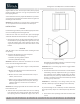
24” Signature Series Operation / Installation Manual
26 35/64"
Ø
D D
B
B
Ø
19
/64
”
15
/32
”deep
7
/16
”
13
/64
”
30
15
/64
”
11
/32
”
Hole drilled at both ends
29
3
/8
”
11
/16
”
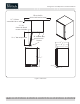
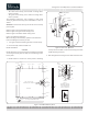
Section D-D
Scale 1:2
Rear
7
/8
”
3
/4
”
Front
R
29
/64
”
3
/4
” Hole detailed in view C
Section B-B
All features called out
in detail views B-B & C apply
only to panels being used
on locking doors
0”
27
/32
”
2
15
/64
”
3
11
/16
”
1
/
8
”
1
/2
” Deep
3
11
/16
”
2
15
/64
”
1
25
/
32
”
27
/32
”
0”
13
9
/32
”
10
9
/32
”
13
/64
”
23
9
/16
”
22
23
/32
”
22
3
/16
”
19
57
/64
”
18”
19
7
/64
”
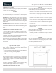
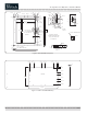
These (2) holes
not to be drilled
for a door with lock
25
49
/
64
”
24
43
/64
”
Rear view
13
39
/64
”
16
39
/64
”
15
7
/64
”
On locking
doors only
Ø
1
/8
”
1
/2
” Deep
17
/32
”
1
25
/32
”
R 1
11
/16
”
2”
3
7
/32
”
3
/64
”
1 1/16"
Ø
3
/
4
”
Thru
27
/64
”
1
13
/64
”
2
1
/
8
”
13
/16
”
11
/64
”
27
/64
”
19
/32
”
Detail C
Scale 1:2
C
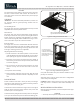
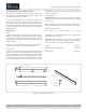
Figure 8. Glass Wood Overlay Panel
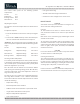
Figure 9. Drawer Solid Wood Overlay
B
C
15
1
/
32
”
22
23
/
32
”
19
57
/
64
”
13
9
/
32
”
10
9
/
32
”
3
11
/
16
”
27
/
32
”
0
0
27
/
32
”
3
11
/
16
”
6
1
/
64
”
9
1
/
64
”
11
23
/
64
”
14
3
/
16
”
23
9
/
16
”
Rear View
3
/
4
”