
Installation Guide


PERLICK RESIDENTIAL INSTALLATION MANUAL
4
perlick.com
SAFETY
PLEASE READ all instructions completely before attempting
to install or operate the unit. Take particular note of the
DANGER, WARNING and CAUTION information in the
manual. The information is important for the safe and
ecient installation, operation and care of your Perlick unit.
DANGER
Indicates a hazard that WILL result in serious injury or
death if precautions are not followed.
Indicates a hazard MAY cause serious injury or death if
precautions are not followed.
WARNING
Indicates a hazard where minor injury or product
damage may occur if precautions are not followed.
CAUTION
PRIOR TO INSTALLATION
Carefully inspect cabinet for hidden damage. If damage is
discovered, le your claim immediately with the transport
company. Perlick is not responsible for damage in transit.
When moving the unit, be sure
to protect nished ooring with
appropriate material to avoid damage from moving
the unit.
Do not lift unit by drawer, shelving
or door handles, as damage to the
unit could occur if not moved as instructed.
To prevent personal injury, a
minimum of two people are
required to lift the unit. Larger units may require
additional personnel.
Before moving the unit, secure the door shut with tape
to prevent door from swinging open while being moved.
Carefully move unit to installation site and place in front of
opening.
If unit has been laid on its back or
sides, place unit upright and allow
minimum of 24 hours before connecting power.
CAUTION
CAUTION
WARNING
CAUTION
PLUMBING
No plumbing connections are required. Condensate from
the cooling coil is automatically evaporated through a
condensate pan located in the condensing section of the
unit.
ELECTRICAL
A 115 volt, 60 Hz, 15 amp circuit breaker and electrical
supply are required. A separate circuit is required for each
Perlick unit installed.
Follow the National Electrical Code and any local codes or
ordinances when installing the receptacle.
All Perlick units come equipped with a NEMA 5-15P 90° plug
with a 5’ cord extending beyond the rear of the cabinet.
The electrical outlet must be ush with, or recessed into,
the wall surface for all HP, HC and HA models.
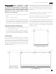
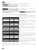
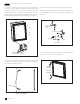
HH (Sottile) models have a recess at the rear of the cabinet
to accomodate the plug and keep a true 18” depth. See
Figure 1 below for the cut-out in the back panel for the
electrical outlet location.
CAUTION
Do not attempt to operate the
equipment on any other power
source than that listed on the Electrical Specication
Plate attached to the unit.
Figure 1. HH (Sottile Model) Electrical Connections