
Install Guide


4
Form No. Z2334A
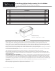
Drain Pump Kit for Undercounter Clear Ice Makers
For use with H50IMS, H50IMW and H50IMS-AD Clear Ice Makers
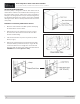
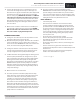
9. Cut the 3/8” ID vent hose to a length of 19.5”
10. On non -AD units, route the vent hose (3/8” I.D.×19.5”)
through the drain tting area (vent hose access area) in the
rear access panel (see Fig. 6).
11. On -AD units, route the vent hose through the 23 mm di-
ameter vent hose access hole in the rear access panel. (See
Fig.7). If the rear access panel does not have a vent hose
access hole, drill a 23 mm or 3/4” diameter hole into the
rear access panel.
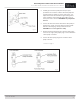
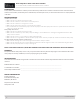
12. Secure the vent hose to the drain pump with the small
tubing clamp provided. Use pliers to tighten the clamp.
CAUTION! Do not over-tighten the clamp.
Fig. 8
WARNING
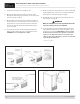
Fig. 9
13. Route one end of the discharge hose (1/2” ID x 10’) through
the drain tting area in the rear access panel. Connect the
discharge hose to the drain pump (See Fig. 8).
14. Reinstall the rear cover and rear access panel in their cor-
rect positions. (See Fig. 10).
Make sure that there are no wires pinched between the
rear access panel, rear cover, or icemaker.
15. Secure the vent hose to the icemaker using the two hose
clips and two 4×8 truss head screws provided. (See Fig. 9).
Screw holes are provided. CAUTION! The vent hose must
be attached and secured to the icemaker or water dam-
age may occur. Make certain there are no kinks in the
vent hose. The drain pump will not operate correctly with
a partially blocked vent hose.
Continued on page 5
Fig. 6 Fig. 7