
Installation guide

- 12 - IDS-108F Installation Guide
Grounding the chassis requires the following items:
• One grounding lug (not provided)
• One 18-12 AWG wire (not provided)
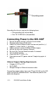
Connecting Power to the IDS-108F
1. Ensure the power source is off prior to connection.
2. Strip both wires 5mm (3/16th inch).
3. Loosen the terminal block screws and connect positive (+) /
negative (-) wires into the -/+ terminals.
4. Tighten terminal screws (0.22Nm-0.25Nm torque).
5. Ensure the wires are securely fastened.
6. Re-insert the Terminal block connector if removed.
7. Turn on power source.
8. Check that the P1 LED is On.
9. If desired connect P2 (power source 2, beginning again at
Step 1).
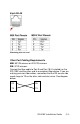
Ethernet Copper Cabling Requirements
• Category 5 UTP or STP
• 24-22 AWG
• Straight through or Ethernet crossover cable
Connect the copper cables from each TP port (RJ-45) on the IDS
switch to Ethernet-enabled devices. See below for pinouts and
cable wire diagrams.