Perle IDS-108F(XT) Unmanaged 10/100 Ethernet Switches Installation Guide P/N 5500339-10
Overview This document contains instructions necessary for the installation and operation of the Perle IDS-108F Ethernet switch. This Ethernet switch can be ordered as an 8-port RJ-45 switch or as an 8-port RJ-45 switch with one or two SC or ST fiber ports. The fiber ports can be either single mode (SM) or multimode (MM) depending on the model selected and they can operate over different wavelengths and distances.
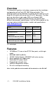
Getting to know your IDS-108F Switch Package Contents: • • • IDS-108F DIN-rail mounting clip (pre-installed on the unit) This guide Note – Optional panel/wall mounting kits may be ordered for the IDS-108F Front View of IDS-108F (8 port RJ-45) IDS-108F installation Guide -3-
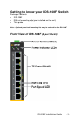
Front View of IDS-108F (with two Fiber ports) -4- IDS-108F Installation Guide
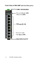
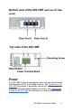
Bottom view of the IDS-108F (with two ST fiber ports) Top view of the IDS-108F Power The IDS-108F switch has two power inputs that can be connected simultaneously to DC or AC power sources. See Top view of the IDS-108F for location. If one power source fails, the other acts as a backup, and automatically powers the switch. See Connecting Power to the IDS-108F for information on how to connect power.
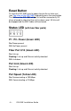
Reset Button To reset the IDS-108F insert a paper clip into the air hole vent (see Top view of the IDS-108F) and gently press the reset button. The LEDs on the IDS-108F will go On and then momentarily Off when released to show that the unit has been reset. All links will be dropped and the MAC tables will be cleared.
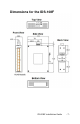
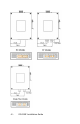
Dimensions for the IDS-108F IDS-108F installation Guide -7-
-8- IDS-108F Installation Guide
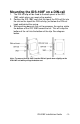
Mounting the IDS-108F on a DIN-rail 1. The DIN-rail clip will be fixed to the back panel of the IDS108F switch when you receive the product. 2. Position the IDS-108F such that the top of the DIN rail fits into the slot on the top of the DIN-rail clip, just below the DIN-rail hook and behind the spring. 3. While pushing down on the unit to compress the spring, rotate the bottom of the IDS-108F toward the rail. This will snap the bottom of the rail into the bottom of the clip. See diagram below.
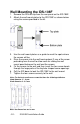
Wall Mounting the IDS-108F 1. Remove the DIN-rail clip from the rear panel on the IDS-108F. 2. Attach the wall mount plates to the IDS-108F as shown below using the screws provided in the kit. 3. Use the wall mount plates as a guide to mark the spots where the screws will be. 4. Drive the screws into the wall leaving about 2 mm of the screw protruding from the wall to allow room for sliding the wall mount panel between the wall and the screws. 5.
Wiring up the IDS-108F Power sources must be off prior to beginning the power connection steps. Ensure that the voltage and current ratings of the intended power source are appropriate for the IDS108F as indicated on the product label. Ensure that the installation and electrical wiring of the equipment is performed by trained and qualified personnel and that the installation complies with all local and national electrical codes.
Grounding the chassis requires the following items: • One grounding lug (not provided) • One 18-12 AWG wire (not provided) Connecting Power to the IDS-108F 1. Ensure the power source is off prior to connection. 2. Strip both wires 5mm (3/16th inch). 3. Loosen the terminal block screws and connect positive (+) / negative (-) wires into the -/+ terminals. 4. Tighten terminal screws (0.22Nm-0.25Nm torque). 5. Ensure the wires are securely fastened. 6. Re-insert the Terminal block connector if removed. 7.
8-pin RJ-45 Remaining pins not used Fiber Port Cabling Requirements MM: 50/125 microns or 62.5/125 microns SM: 9/125 microns Connect the fiber cable to Port 9 and Port 10 (if installed) on the IDS-108F and the other end to a compliant fiber device. If you are making your own fiber cables, remember that the RX on one side needs to go to TX on the other side and vice versa. See diagram below.
Technical Specifications Connection Dual input terminal block power 8 port Ethernet Dual input terminal block power 8+1 fiber port Dual input terminal block power 8 + 2 fiber ports Reverse Polarity Protection Power Input/Consumption 9.6 to 60 VDC, 0.5A max 18 to 30 VAC, 0.25A max Power Input/Consumption 9.6 to 60 VDC, 0.7A max 18 to 30 VAC, 0.35A max Power Input/Consumption 9.6 to 60 VDC, 0.9A max 18 to 30 VAC, 0.
IDS-108F models Fiber Connector Mode Distance Wavelength (nm) TX Power (dB) RX Power (dB) Budget Fiber Specifications IDS-108F (XT) None n/a n/a n/a n/a n/a n/a IDS-108F-M2SC2 (XT) SC MM duplex 2 km 1.2 miles TX: 1310 RX:1310 Min:-6 Max:-0 Min:-17 Max:-0 11 IDS-108F-M2ST2 (XT) ST MM duplex 2 km 1.2)miles TX: 1310 RX:1310 Min:-6 Max:-0 Min:-17 Max:-0 11 IDS-108F-M1SC2U SC MM simplex 2 km 1.
IDS-108F-DM2ST2 (XT) 2 x ST MM duplex 2 km 1.2 miles TX: 1310 RX:1310 Min:-6 Max:-0 Min:-17 Max:-0 11 IDS-108F-DM1SC2U 2 x SC MM simplex 2 km 1.2 miles TX: 1310 RX:1550 Min:-15 Max:-8 Min:-28 Max:-3 13 IDS-108F-DM1SC2D 2 x SC MM simplex 2 km 1.2 miles TX: 1550 RX: 1310 Min:-15 Max:-8 Min:-28 Max:-3 13 IDS-108F-DS2SC20 (XT) 2 x SC SM duplex 20 km 12.4 miles TX: 1310 RX:1310 Min:-15 Max:-8 Min:-34 Max:3 19 IDS-108F-DS2ST20 (XT) 2 x ST SM duplex 20 km 12.