
Installation guide


- 14 - IDS-105G Installation Guide
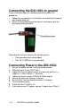
Connecting the IDS-105G to ground
If your installation requires additional grounding follow this
procedure.
1. Follow the manufacturer’s instructions for attaching the ground
wire to grounding lug.
2. Attach the grounding lug to the chassis and secure with the
grounding screw provided.
Grounding the chassis requires the following items:
• One grounding lug (not provided)
• One 18-12 AWG wire (not provided)
Connecting Power to the IDS-105G
1. Ensure the power source is off prior to connection.
2. Strip both wires 5 mm (3/16
th
inch).
3. Loosen the terminal block screws and connect positive (+) /
negative (-) wires into the -/+ terminals.
4. Tighten terminals screws (0.22Nm-0.25Nm torque).
5. Ensure the wires are securely fastened.
6. Re-insert the Terminal block connector if removed.
7. Turn on power source.
8. Check that the P1 LED is On.
9. If desired connect P2 (power source 2, beginning at Step 1).