
Installation guide


- 12 - IDS-105G Installation Guide
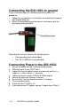
Mounting the IDS-105G to the Wall
1. Remove the DIN-rail clip from the rear panel on the IDS-105G.
2. Attach the wall mount plates to the IDS-105G switch as shown
below using the screws provided in the kit.
3. Use the wall mount plates as a guide to mark the spots where
the screws will be.
4. Drive the screws into the wall leaving about 2 mm of the screw
protruding from the wall to allow room for sliding the wall
mount panel between the wall and the screws.
5. Once the screws are fixed to the wall, insert the four screw
heads through the large parts of the keyhole shaped screw
openings.
6. Pull the IDS down to lock the IDS-105G to the wall mount.
7. Tighten the four screws securely to the wall.
Note: For the best results use screws that have the following attributes:
Head diameter .5 - .6 mm
Shaft diameter 3 - 3.5 mm
Note: the dimensions are in mm