
Installation guide


IDS-105G Installation Guide - 11 -
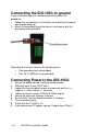
Mounting the IDS-105G on a DIN-rail
1. The DIN-rail clip will be fixed to the back panel of the IDS-
105G switch when you receive the product.
2. Position the IDS-105G switch such that the top of the DIN-rail
fits into the slot on the top of the DIN-rail clip, just below the
hook and behind the spring.
3. While pushing down on the unit to compress the spring rotate
the bottom of the IDS-105G toward the rail. This will snap the
bottom of the rail into the bottom of the clip. See diagram
below.
Note: To remove the IDS-105G switch from the DIN-rail, push down slightly
on the IDS-105G while pulling the bottom out.