Perle 10G Media Converters Installation Guide S-10G-STS S-10G-XTS S-10G-XTX S-10G-XTSH S-10G-XTXH P/N 5500325-10
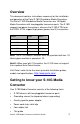
Overview This document contains instructions necessary for the installation and operation of the Perle S-10G Standalone Media Converters. The Perle S-10G Standalone Media Converters are 10 Gigabit Media Converters with two pluggable transceiver ports. The S-10G supports low power transceivers, whereas the S-10G-XTSH and the S10G- XTXH support high power (power level 4) transceivers.
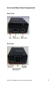
Front and Rear Panel Components Front View Rear View Perle S- 10G Media Converter Installation Guide 3
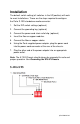
Installation The default switch setting (all switches in the UP position) will work for most installations. These are the steps required to configure the Perle S-10G standalone media converter: 1. Set the DIP switch settings.(optional) 2. Connect the grounding lug. (optional) 3. Connect the power cord strain relief clip. (optional) 4. Insert the fiber or copper modules. 5. Connect the fiber or copper cables. 6.
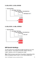
S-10G-XTS, S-10G-XTSH S-10G-XTX, S-10G-XTXH DIP Switch Settings The DIP switches are accessible through the opening in the side of the enclosure. The function of the DIP switches varies by model, so please refer to the appropriate model. Note: Switch changes made when the product is powered up take effect immediately and will result in a link reset on both ports.
Operating Mode (Switch 1) Switch Position Mode Up (default) Data Down Test Data: In Data mode, data will flow between the two fiber connections. Test: Test Mode is used to run diagnostics, enable loopback and for running the Built In Link Tests. Note: The Operation Mode (Switch 1) affects the function of DIP Switches 2 and 3.
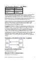
Test Function (Switch 2 – Test Mode) Switch Position Type Up (default) Built In Link Test Down Loopback Built In Link Test: Switch 2 causes the S-10G to initiate the Built In Link Tests on the specified port. Switch 3 determines the specified port for the Built In Link Tests. If Switch 3 is Up, the tests will be run on Port 1. If the Switch is Down the tests will be run on Port 2. The other port will be disabled during these tests.
Note: If the remote media converter is not a Perle S-10G then the remote media converter will need to be put into loopback mode. See the documentation that came with that media converter. Sequence of Events 1. The Local S-10G sends the Remote S-10G a signal to go into loopback mode. 2. The Remote S-10G media converter turns on loopback mode. 3. Built In Test data is sent from the Local S-10G media converter to the Remote S-10G media converter. 4.
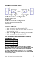
Illustration of the FFA feature Media Converter A Configuration Link Mode–Standard Mode Fiber Fault Alert Media Converter B Configuration Link Mode–Smart Link Pass through Mode Fiber Fault Alert Sequence of Events 1. Media Converter A loses fiber connection (RX). 2. Media Converter A notifies the remote Media Converter that there is a fault on the Link. 3. Media Converter B detects loss of fiber link on receiver RX. 4. Media Converter B turns off transmitter (TX).
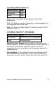
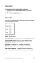
Operation Powering up the Perle Media Converter 1. Connect the Perle supplied power adapter to the media converter. 2. Turn on the power at the source. 3. Check that the PWR LED light is lit. Status LED The Perle 10G Media converters have three status LEDs located on the front panel of the unit. PWR - Power/Test Green On: Power is on and the unit is in normal operation mode. Green blinking slowly: the unit is in test or loopback mode.
LK1- Port 1 Activity On: Fiber link present. Blinking quickly: Fiber link present and receiving data. Blinking slowly: The fiber link has been taken down as a result of Smart Link Pass-Through. Blinking one second on, 3 seconds off: the maximum specified operating temperature within the inserted module has been exceeded. Off: No fiber link present. LK2 – Port 2 Activity On: Fiber link present. Blinking quickly: Fiber link present and receiving data.
• Cross-head screwdriver (not provided) Note: For your safety, when installing this equipment, always ensure that the chassis ground connection is installed first and disconnected last. Attaching the Grounding Lug 1. Attach the grounding lug to one end of an 18-12 AWG wire. 2. Attach the grounding lug to the chassis and secure with the grounding screw(s). Attaching the Power Cord Strain Relief Clip 1. Feed the power cord through the opening in the power cord relief clip. 2.
Troubleshooting General Ensure power is supplied to the media converter – use of the Perle supplied power adapter is highly recommended. Ensure that the SFP+ or XFP modules are of the same speed and are operating properly. Ensure both devices on either end of each fiber are compatible. For fiber connections, ensure the RX and TX have been reversed between the two media converters.
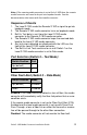
Module Temperature Protection Every S-10G comes equipped with an internal fan to provide cooling to the unit. However, if any of the modules are operating above their specified maximum operating temperature, the S-10G will reduce the power to these modules. The S-10G will continue to monitor the operating temperature of the unit until the temperature is below the maximum operating temperature and then the S-10G will return the modules to normal operating.
Technical Specifications The following applies to all Perle Standalone S-10G Media converters. Power Input/Consumption 9-30VDC 1.0A Max, 600mA at 12VDC 1.2A Max, 800mA at 12VDC 1.5A Max, 1.0A at 12VDC 1.5A Max, 1.0A at 12VDC 2.0A Max, 1.
Compliance Information FCC This product has been found to comply with the limits for a Class A digital device, pursuant to Part 15 of the FCC rules. These limits are designed to provide reasonable protection against harmful interference when the equipment is operated in a commercial environment. This equipment generates, uses, and can radiate radio frequency energy and, if not installed and used in accordance with the instructions in this Guide, may cause harmful interference to radio communications.