
User Manual

SENR9977 9
Systems Operation Section
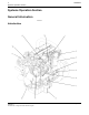
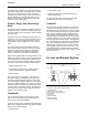
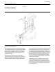
The turbine wheel and the compressor wheel (3) are
installedonth
e same shaft. Therefore, the turbine
wheel and the compressor wheel rotate at the same
rpm. The compressor wheel is enclosed by the
compressor ho
using (2). The compressor wheel
compresses the intake air (1). The intake air flows
into the engine cylinders through the inlet valves of
the cylinder
s.
The oil from the main gallery of the cylinder block
flows throug
h the oil inlet port (5) in order to
lubricate the turbocharger bearings (4) and (6). The
pressurized oil passes through the bearing housing
of the turbo
charger. The oil is returned through the oil
outlet port (10) to the oil pan.
The turboch
arger has a wastegate. The wastegate is
controlled by the boost pressure. This allows some
of the exhaust to bypass the turbocharger at higher
engine spee
ds. The wastegate is a type of valve
that automatically opens at a preset level of boost
pressure in order to allow exhaust gas to flow around
the turbin
e. The wastegate allows the design of the
turbocharger to be more effective at lower engine
speeds.
The wastegate is controlled by a diaphragm. One
side of this diaphragm is open to the atmosphere.
The oth er
side of this diaphragm is open to the
manifold pressure.
Cylinder Head And Valves
The valve
s and the valve mechanism control the
flow of the air and the exhaust gases in the cylinder
during engine operation. The cylinder head assembly
has two v
alves for each cylinder. Each valve has one
valve spring. The ports for the inlet valves are on
the left side of the cylinder head. The ports for the
exhaust
valves are on the right side of the cylinder
head. Steel valve seat inserts are installed in the
cylinder head for both the inlet and the exhaust
valves
. The valve seat inserts can be replaced.
The valves are installed in valve guides. The valve
guides
canbereplaced.Theexhaustvalveguidehas
a counterbore in order to prevent the seizure of the
valve stem. The seizure of the valve stem is caused
by a bui
ldup of carbon under the head of the valve.
The inlet and the exhaust valves are opened and
close
d by the rotation and movement of the following
components:
•
Crank
shaft
•
Camshaft
•
Valve lifters
•
Pushr
ods
•
Rocker arms
•
Valve springs
The camshaft ge
ar is driven by the crankshaft gear.
The camshaft and the crankshaft are timed together.
When the camshaft turns, the valve lifters and the
pushrods are m
oved up and down. The pushrods
move the rocker arms. The movement of the rocker
arms open the valves. The opening and closing of
the valves is
timed with the firing sequence of the
engine. The valve springs push the valves back to
the closed position.