
User Manual


8 SENR9977
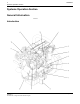
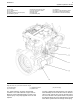
Systems Operation Section
Engines which are naturally aspirated pull outside air
through an air c
leaner directly into the inlet manifold
(6). The air flows from the intake manifold to the
engine cylinders (7). The fuel is mixed with the air in
the engine cyl
inders. After the fuel combustion occurs
in the engine cylinder, the exhaust gases flow directly
to the outside air through the exhaust manifold (8).
Turbocharged engines pull outside air through an air
cleaner into the air intake (4) of the turbocharger. The
suction is ca
used by the turbocharger compressor
wheel (3). Then, the turbocharger compressor
wheel compresses the air. The air flows through
the afterco
oler (5). Cooling the inlet air increases
combustion efficiency. Increased combustion
efficiency helps achieve the following benefits:
•
Fuel consumption is reduced.
•
Power outpu
t is increased.
•
Emissions from the engine are reduced.
From the aftercooler (5), the air flows to the intake
manifold (6) which directs an even distribution of the
air to each
engine cylinder (7). Air is pulled into the
engine cylinder (7) during the intake stroke of the
piston. Then, the air is mixed with fuel from the fuel
injectors
.
Each piston makes four strokes:
1. Intake
2. Compressi
on
3. Power
4. Exhaust
The sequen
ce of the strokes by all of the pistons in
all of the engine cylinders provide constant air flow
through the inlet system during the engine operation.
The exhaust stroke and the timing of the valve
mechanism pushes combustion gases through the
open exha
ust valve into the exhaust manifold (8).
The exhaust gases flow through the blades of the
turbocharger turbine wheel (2) which causes the
turbine w
heel and the compressor wheel to turn.
Then, the exhaust gases flow through the exhaust
outlet (1) of the turbocharger to the outside.
The air inlet system is also equipped with a crankcase
ventilation system. The intake strokes of the pistons
pull in a
tmospheric air to the crankcase.
Turboch
arger
Note: The turbocharger is not serviceable.
A turbocharger increases the temperature and the
density of the a
ir that is sent to the engine cylinder .
This condition causes a lower temperature of ignition
to develop earlier in the compression stroke. The
compression s
troke is also timed in a more accurate
way with the fuel injection. Surplus air lowers the
temperature of combustion. This surplus air also
provides int
ernal cooling.
A turbocharger improves the following aspects of
engine perfo
rmance:
•
Power output is increased.
•
Fuel efficiency is improved.
•
Engine torqu
e is increased.
•
Durability of the engine is improved.
•
Emissions from the engine are reduced.
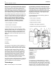
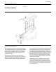
g00302786
Illustration 5
Components of a turboc harger (typical exam ple)
(1) Air intake
(2) Compr essor housing
(3) Compressor wheel
(4) B earing
(5) Oil inlet port
(6) B earing
(7) Turbine housing
(8) Turbine wheel
(9) Exhaust outlet
(10) Oil outlet port
(11) Exhaust inlet
A turbocharger is installed between the exhaust
and intake manifolds. The turbocharger is driven by
exhaust gases which flow through the exhaust inlet
(11). The energy of the exhaust gas turns the turbine
wheel (8). Then, the exhaust gas flows out of the
turbine housing (7) through the exhaust outlet (9).