
User Manual

SENR9977 7
Systems Operation Section
The engine has a cast iron cylinder head. The inlet
manifold is int
egral within the cylinder head. An inlet
valve and an exhaust valve for each cylinder are
controlled by a pushrod valve system. The ports for
the inlet valv
es are on the left side of the cylinder
head. The ports for the exhaust valves are on the
right side of the cylinder head.
Pistons, Rings, and Connecting
Rods
The pistons h
ave a combustion chamber in the top of
thepistoninordertoprovideanefficientmixoffuel
and air. The piston pin is off-center in order to reduce
the noise le
vel.
The pistons have two compression rings and an oil
control rin
g. The groove for the top ring has a hard
metal insert in order to reduce wear of the groove.
The skirt has a layer of graphite in order to reduce
wear.
The correct piston height is important in order to
ensure tha
t the piston does not contact the cylinder
head. The correct piston height also ensures the
efficient combustion of fuel which is necessary in
order to co
nform to requirements for emissions.
Engines are equipped with connecting rods that have
bearing ca
ps that are fracture split. The bearing caps
on fracture split connecting rods are retained with
torx screws. Connecting rods with bearing caps that
are fract
ure split have the following characteristics:
•
Higher integrity for the rod
•
The splitting produces an accurately matched
surface on each side for improved strength.
•
Modern design
The conne
cting rod is matched to each cylinder.
The piston height is controlled by the length of the
connecting rod. Six different lengths of connecting
rods are
available in order to attain the correct piston
height. The different lengths of connecting rods are
made by machining the small end bearing off-center
in order
to form an eccentric bearing. The amount of
the eccentricity of the bearing creates the different
lengths of the connecting rods.
Crankshaft
The crankshaft changes the linear energy of the
pistons and connecting rods into rotary torque in
order t
o power external equipment.
A gear at the front of the crankshaft drives the timing
gears.
The crankshaft gear turns the idler gear which
then turns the following gears:
•
Camsha
ft gear
•
Fuel injection pump
•
Lower idler gear which turns the gear of the
lubricating oil pump
Lip type seals are used on both the front of the
crankshaft and the rear of the crankshaft.
Camshaft
The engine has a single camshaft. The camshaft
is driven by an idler gear in the front housing. The
camshaft uses
only one bearing on the front journal.
The other journals rotate in the bore of the cylinder
block. The front bearing and the camshaft bores
in the cylind
er block support the camshaft. As the
camshaft turns, the camshaft lobes move the valve
system components. The valve system components
move the inle
t and exhaust valves in each cylinder.
The camshaft gear must be timed to the crankshaft
gear. The relationship between the lobes and the
camshaft ge
ar causes the valves in each cylinder
to be opened and closed at the correct time. The
relationship between the lobes and the camshaft
gear also c
auses the valves in each cylinder to close
at the correct time.
i02242605
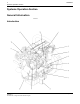
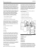
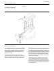
Air Inlet an d Exha ust System
g0113051 6
Illustration 4
Air inlet and ex haust system (typical example)
(1) Exhaust outlet
(2) Turbocharger turbine whe el
(3) Turbocharger compressor wheel
(4) Air intake
(5) A ftercooler
(6) Intake m anifold
(7) Engine cylinders
(8) Ex haust manifold