
User Manual

60 SENR9977
Testing and Adjusting Section
5. Rotate the crankshaft by hand in order to ensure
that the cranks
haft is not stuck. Check the oil
viscosity and any external loads that could affect
the engine rotation.
a. If the crankshaft is stuck or difficult to turn,
repair the engine.
b. If the engine is not difficult to turn, go to Step 6.
6. Attempt to cra
nk the starting motor.
a. The starting motor cranks slowly.
Remove the starting motor for repair or
replacement.
b. The starting motor does not crank.
Check for the b
locked engagement of the
pinion gear and flywheel ring gear.
Note: Blocke
d engagement and open solenoid
contacts will give the same electrical symptoms.
i01911231
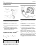
Glow Plugs - Test
Contin uity Check o f the Glow Plu gs
The following test will check the continuity of the glow
plugs.
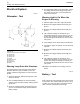
1. Disconnect the power supply and the bus bar.
2. Use a suitable digital multimeter to check
continuity (resistance). Turn the audible signal on
the digital multimeter ON.
3. Place one probe on the connection for the glow
plug and the other probe to a suitable ground. The
digital multimeter should make an audible sound.
Replace the glow plug if there is no continuity.
4. Check the continuity on all the glow plugs.
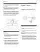
Checking The Operation of The
Glow Plug
The following test will check the operation of the glow
plugs.
1. Disconnect the power supply and the bus bar.
2. Connect the power supply to only one glow plug.
3. Place a suitable ammeter on the power supply
wire.
4. Connect a suitable digital multimeter to the
terminal on th
eglowplugandtoasuitableground.
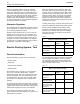
5. TurntheswitchtotheONpositioninorderto
activate the g
low plugs.
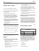
Table 11
12 Volt System
Amp
Time (sec)
30 Initial
21 4
14 8
10 20
9 60
Table 12
24 Volt System
Amp
T
ime (sec)
12 Initial
8.5 8
7
20
6 60
6. Check the reading on all of the glow plugs.
7. If there is no reading on the ammeter check the
electrical connections. If the readings on the
ammeter are low replace the glow plugs. If there
is still no reading replace the glow plugs.