
User Manual

56 SENR9977
Testing and Adjusting Section
Electrical System
i01899123
Alternator - Test
g00931045
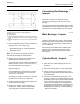
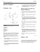
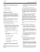
Illustration 65
Typical wiring schematic for an a lternator
(A) Terminal “B+”
(B) Terminal “D+”
(C) Terminal “W”
(D) Ground
(1) Elect rical sw itc h
(2) Dash light
(3) Ignition switch
(4) Battery
Warning L amp Does Not Illum inate
The warning lamp for the charging system should
illuminate when the ignition switch is in the ON
position. Follow the steps below in order to test the
system.
1. Check the light bulb. Replace the light bulb if the
element is broken.
2. Use a suitable Multimeter to check the battery
voltage. Check the battery voltage with the ignition
switch OFF.
3. Check the voltage between the terminal (A) and
ground. The measured voltage should equal the
battery voltage.
4. Turn the ignition switch to the ON position. Check
the voltage bet
ween terminal (B) and ground. If
the voltage is more than 2 Volts the alternator
needs to be replaced.
Warning Light is On When the
Engine is Running
1. Start the eng
ine and run the engine at fast idle.
2. Measure the voltage between terminal (A) and
ground.
3. Measure the voltage between terminal (B) and
ground.
4. The measured voltage for terminal (A) and
terminal (B)
should be 13 to 15 volts for a 12 volt
system. The measured voltage for terminal (A)
and terminal (B) should be 26 to 30 volts for a 24
volt system
.
5. If the voltages do not match replace the alternator.
6. Increase the engine to high idle. Turn an electrical
load ON.
7. Measure the voltage between terminal (A) and
ground.
8. Measure the voltage between terminal (B) and
ground.
9. The measured voltage for terminal (A) and
terminal (B) should be 13 to 15 volts for a 12 volt
system. Th
e measured voltage for terminal (A)
and terminal (B) should be 26 to 30 volts for a 24
volt system.
10. Replace the alternator if the voltage does not
match.
i0189913
6
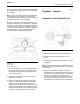
Battery - Test
Most of th
e tests of the electrical system can be done
on the engine. The wiring insulation must be in good
condition. The wire and cable connections must be
clean, an
d both components must be tight.