
User Manual

SENR9977 55
TestingandAdjustingSection
g00913389
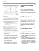
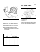
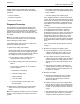
Illustration 63
1. Install the 21825617 dial gauge. See Illustration
63.
2. Setthepointerofthe21825617 dial gauge to
0mm(0inch).
3. Check the alignment at intervals of 90 degrees
around the flywheel housing.
4. Calculate the difference between the lowest
measurement and the highest measurement. This
difference must not be greater than the limit that
isgiveninTable7.
Note: Any necessary adjustment must be made on
the flywheel housing.
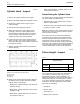
Table 7
Limits for Flywheel Housing Runout and Alignment
(Total Indicator Reading)
Bore of the Housing
Flange
Maximum Limit (Total
Indicator Reading)
362 mm (1
4.25 inch)
0.23 mm (
0.009 inch)
410 mm (16.14 inch) 0.25 mm (0.010 inch)
448 mm (17.63 inch) 0.28 mm (0.011 inch)
511 mm (20.11 inch) 0.30 mm (0.012 inch)
584 mm (22.99 inch) 0.36 mm (0.014 inch)
648 mm (25.51 inch) 0.41 mm (0.016 inch)
787 mm (30.98 inch) 0.48 mm (0.019 inch)
i02270822
Gear G r ou p - Inspect
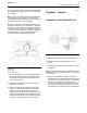
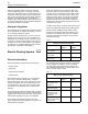
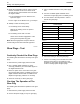
g0113759 2
Illustration 64
(1) Fuel pu mp drive gear
(2) Idler gear
(3) Cams haft drive gear
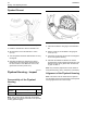
Remove the front timing cover and inspect the gears.
The timing marks on the gears indicate the front side
of the gears. Inspect the gears for broken teeth or
worn teeth.