
User Manual

52 SENR9977
Testing and Adjusting Section
i01905914
Cylind er Head - Insp ect
1. Remove the cylinder head from the engine.
2. Remove the water temperature regulator housing.
3. Inspect the cy
linder head for signs of gas or
coolant leakage.
4. Remove the val
ve springs and valves.
5. Clean the bottom face of the cylinder head
thoroughly. C
lean the coolant passages and
the lubricating oil passages. Make sure that the
contact surfaces of the cylinder head and the
cylinder b loc
k are clean, smooth and flat.
6. Inspect the bottom face of the cylinder head for
pitting, cor
rosion, and cracks. Inspect the area
around the valve seat inserts and the holes for the
fuel injectors carefully.
7. Test the cylinder head for leaks at a pressure of
200kPa(29psi).
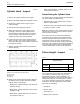
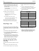
g01012606
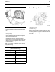
Illustration 58
Flatness of the cy linder head (typical example)
(A)Sidetoside
(B) End to end
(C) Diagonal
8. Measure the cylinder head for flatness. Measure
the flatness of the cylinder head with a straight
edge and with a feeler gauge.
•
Measure the cylinder head from one side to the
opposite side (A).
•
Measure the cylinder head from one end to the
opposite end (B).
•
Measure the cylinder head from one corner to
the opposite corner (C).
Refer to Specifications, “Cylinder Head” for the
requirements o
fflatness.
Remachining th
e Cylinder Head
The bottom face of cylinder head can be resurfaced if
any of the foll
owing conditions exist:
•
The bottom face of the cylinder head is not flat
within the spe
cifications.
•
The bottom face of the cylinder head is damaged
by pitting, co
rrosion, or wear.
Note: The thickness of the cylinder head must not be
less than 117
.20 mm (4.614 inch) after the cylinder
head has been machined.
If the bottom
face of the cylinder head has been
remachined, the recesses in the cylinder head for
the valve seat inserts must be machined. The valve
seat insert
smustbegroundonthesidewhichis
inserted into the cylinder head. Grinding this surface
will ensure that no protrusion exists above the bottom
face of the c
ylinder head. Refer to Specifications,
“Cylinder Head Valves” for the correct dimensions.
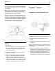
i01889496
Piston Height - Inspect
Table 5
Required Tools
Part
Number
Part Description
Qty
21825617
Dial gauge 1
21825496
Dial gauge holder 1
If the height of the piston above the cylinder block
is not within the tolerance that is given in the
Specifications Module, “Piston and Rings”, the
bearing for the piston pin must be checked. Refer to
Testing and Adjusting, “Connecting Rod - Inspect”.
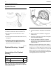
If any of the following components are replaced or
remachined, the piston height above the cylinder
block must be measured:
•
Crankshaft
•
Cylinder head
•
Connecting rod
•
Bearingforthepistonpin