
User Manual

SENR9977 51
TestingandAdjustingSection
g00927038
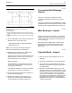
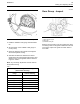
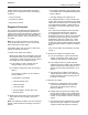
Illustration 57
Inspection of the connecting rod parallel alignment.
(1) Measuring p ins
(2) Connecting rod
(L) Measure the distance between the center of the bore for the
piston pin bearing and the center of the connecting rod bearing
bore.
(K) Measure the distance 127 mm (5.0 inch) from the connecting
rod.
1. Use the appropriate tools in order to measure the
distances for the connecting rod (2).
•
Appropriate gauges for measuring distance
•
Measuring pins (1)
Note: The connecting rod bearings should be
removed before taking the measurements.
2. Measure the connecting rod for distortion and
parallel alignment between the bores.
The measurements must be taken at distance (K).
Distance (K) has a value of 127 mm (5.0 inch)
from both sides of the connecting rod.
Measure length (L).
The total difference in measurements of length
(L) from each side should not vary more than
± 0.25 mm (± 0.010 inch).
Ifthepistonpinbearingisnotremoved,thelimits
are reduced to ± 0.06 mm (± 0.0025 inch).
3. Inspect the piston pin bearing and the piston pin
for wear and other damage.
4. Measure the clearance of the piston pin in
the piston pin bearing. Refer to Specifications,
“Connecting Rod” for clearance dimensions.
i01748770
Conne ctin g R od Bearings -
Inspect
Check the conn
ecting rod bearings and the
connecting rod bearing journal for wear or other
damage.
Connecting rod bearings are available with a smaller
inside diameter than the original size bearings. These
bearings are
for crankshafts that have been ground.
i01748792
Main Bearing s - Inspect
Check the main bearings for wear or other damage.
Replace both halves of the bearings and check the
condition of the other bearings if a main bearing is
worn or damaged.
Main bearings are available with a smaller inside
diameter than the original size bearings. These
bearings are for main bearing journals that have
been ground.
i01946424
Cylinder Block - Inspect
1. Clean all o
f the coolant passages and the oil
passages.
2. Check the c
ylinder block for cracks and damage.
3. The top deck of the cylinder block must not be
machined.
This will affect the piston height above
the cylinder block.
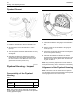
4. Check the c
amshaft bearing for wear. If a new
bearing is needed, use a suitable adapter to press
the bearing out of the bore. Ensure that the oil hole
in the new
bearing faces the front of the block.
The oil hole in the bearing must be aligned with
the oil hole in the cylinder block. The bearing must
be align
ed with the face of the recess. Refer to
Disassembly and Assembly, “Camshaft Bearings
- Remove and Install”.