
User Manual

SENR9977 41
TestingandAdjustingSection
i01889422
Valve Depth - Inspect
Table 4
Required Tools
Part
Number
Part Description
Qty
21825617
Dial gauge 1
21825496
Dial gauge holder 1
g00983531
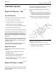
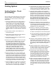
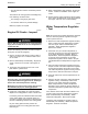
Illustration 48
Measurement of the valve dep th
(1) 2182 5617 Dial gauge
(2) 2182549 6 Dial gauge holder
1. Use the dial gauge (1) with the dial gauge holder
(2) to check the depths of the inlet valves and
the exhaust valves below the face of the cylinder
head. Use the cylinder head face (3) to zero the
dial gauge (1).
2. Position the dial gauge holder (2) and the dial
gauge (1) in order to measure the valve depth.
Measure the depth of the inlet valve and the
exhaust valve before the valve springs are
removed.
Refer to Specifications, “Cylinder Head Valves”
for the minimum, the maximum, and the service
wear limits for the valve depth below the cylinder
head face.
If the valve depth below the cylinder head face
exceeds the service limit, use a new valve to
check the valve depth. If the valve depth still
exceeds the service limit, renew the cylinder head
or renew the valve seat inserts (if equipped). If the
valve depth is within the service limit with a new
valve, renew the valves.
3. Inspect the valves for cracks and other damage.
Check the valve
stems for wear. Check that the
valve springs are the correct length under the test
force. Refer to Specifications, “Cylinder Head
Valves” for th
e dimensions a nd tolerances of the
valves and the valve springs.
i01938952
Valve Guide - Inspect
Perform this inspection in order to determine if a
valve guide should be replaced.
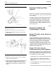
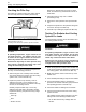
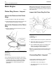
g00986821
Illustration 49
(1) Valve guide
(2) Radial mo vem ent of the va lve in the valve guide
(3) Valve stem
(4) Dial indicator
(5) Valve head
1. Place a new valve in the valve guide.
2. Place a suitable dial indicator with the magnetic
base on the face of the cylinder head.
3. Lift the edge of the valve head to a distance of
15.0 mm (0.60 inch).
4. Move the valve in a radial direction away from the
dial indicator. Make sure that the valve moves
away from the dial indicator as far as possible.
Position the contact point of the dial indicator on
the edge of the valve head. Set the position of the
needle of the dial indicator to zero.