
User Manual

40 SENR9977
Testing and Adjusting Section
•
Broken socket on the upper end of a pushrod
•
Loose adjustment screw for the valve lash
If the camshaft
and the valve lifters show rapid wear,
look for fuel in the lubrication oil or dirty lubrication
oil as a possible cause.
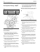
The valve lash is measured between the top of the
valve stem and the rocker arm lever.
Note: An adjustment is not necessary if the
measurement of the valve lash is in the acceptable
range. Inspe
ct the valve lash while the engine is
stopped. The temperature of the engine does not
change the valve lash setting.
Note: When the following procedures are performed,
the front housing must be installed.
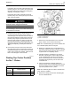
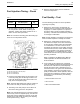
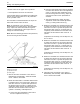
g01016764
Illustration 47
Settingthevalvelash
(1) A djustment screw
(2) Feeler gau ge
1. Remove the valve mechanism cover. Refer to
Disassembly and Assembly, “Valve Mechanism
Cover - Remove and Install”.
2. Rotate the crankshaft in a clockwise direction that
is viewed from the front of the engine. When the
inlet valve of the No. 4 cylinder has opened and
the exhaust valve of the No. 4 cylinder has not
completely closed measure t he valve lash of the
inlet valve and the exhaust valve of the No. 1
cylinder. If necessary, make adjustment.
a. Loosen the valve adjustment screw locknut
that is on adjustment screw (1).
b. Place the appropriate feeler gauge (2) between
the rocker arm a
nd the valve. Turn adjustment
screw (1) while the valve adjustment screw
locknut is being held from turning. Adjust the
valve lash unt
il the correct specification is
achieved.
c. After each ad
justment, tighten the valve
adjustment screw locknut while adjustment
screw (1) is being held from turning.
3. Rotate the crankshaft in a clockwise direction that
is viewed from the front of the engine. When the
inlet valve o
f the No. 2 cylinder has opened and
the exhaust valve of the No. 2 cylinder has not
completely closed measure the valve lash of the
inlet valve
and the exhaust valve of the No. 3
cylinder.
If adjustme
nt is necessary, refer to Steps 2.a, 2.b,
and 2.c above.
4. Rotate the
crankshaft in a clockwise direction that
is viewed from the front of the engine. When the
inlet valve of the No. 1 cylinder has opened and
the exhaus
t valve of the No. 1 cylinder has not
completely closed measure the valve lash of the
inlet valve and the exhaust valve of the No. 4
cylinder
.
If adjustment is necessary, refer to Steps 2.a, 2.b,
and 2.c ab
ove.
5. Rotate the crankshaft in a clockwise direction that
is viewed
from the front of the engine. When the
inlet valve of the No. 3 cylinder has opened and
the exhaust valve of the No. 3 cylinder has not
complet
ely closed measure the valve lash of the
inlet valve and the exhaust valve of the No. 2
cylinder.
If adjustment is necessary, refer to Steps 2.a, 2.b,
and 2.c above.
6. Install the valve mechanism cover. Refer to
Disassembly and Assembly, “Valve Mechanism
Cover-R
emove and Install”.