
User Manual

34 SENR9977
Testing and Adjusting Section
i02285307
Fuel Injectio n Timing - Adjust
Table 2
Required Tools
Part
Number
Part Description Qty
27610032
Timing Pin 1
g011347 28
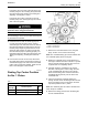
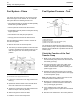
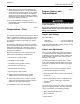
Illustration 41
(1) Hole for timing pin for the fuel pump
(2) Hole for c ams haft pin
(3) Hole for crankshaft pin
1. Set the number one piston at top center on
the compression stroke. Refer to Testing and
Adjusting, “Finding Top Center Position for No. 1
Piston” for the correct procedure.
Note: Do not remove the timing pins after finding top
center on the compression stroke.
2. Remove the four setscrews and the four washers
and then remove the fuel pump gear from the hub
on the fuel injection pump.
3. Remove the idler gear. Refer to Disassembly and
Assembly,“IdlerGear(Front)-Remove”.
4. Install the fuel pump gear on the hub of the fuel
injection pump shaft and install the four setscrews
and the four washers.
5. Turn the fuel pump gear until the slot in the hub
is aligned with the hole in the fuel injection pump
body.
6. Insert the 27610032 Timing Pin through the hole
in the fuel pump
gear and through the slot in the
hub.Pushthetimingpinfullyintotheholeinthe
body of the fuel injection pump.
Note: The 27610032 Timing Pin must be a sliding fit
in the hole in the body of the fuel injection pump.
g0114321 7
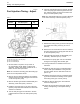
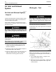
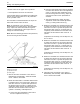
Illustration 42
7. Release the locking screw (4). Remove the spacer
(5).Tightenthelockingscrew(4)to31N·m
(23 lb ft).
8. Remove the four setscrews and the four washers
and then remove the fuel pump gear from the hub
on the fuel injection pump.
9. Install the idler gear. Refer to Disassembly and
Assembly,“IdlerGear(Front)-Install”.
10. Install the fuel pump gear over the 27610032
Timing Pin and engage with the idler gear.
11. Loosely install the four washers and the four
setscrews.
12. Rotate the fuel pump gear counterclockwise in
order to take up the backlash in the gear train
and then tighten the four setscrews to 28 N·m
(20.7lbft).
13. Release the locking screw (4). Install the spacer
(5) under the head of the locking screw. Tighten
the locking sc rew (4) to 12 N·m (9 lb ft).
14. Remove all three timing pins and install the
removed components.
15. Check the fuel injection timing again. Refer to
Testing and Adjusting, “Fuel Injection Timing -
Check”.