
User Manual

SENR9977 33
TestingandAdjustingSection
If excessive air is not seen at the inlet to the fuel
transfer pump,
the air is entering the system after
the fuel transfer pump. Refer to the Testing and
Adjusting, “Fuel System - Prime”.
If excessive air is seen at the inlet to the fuel
transfer pump, air is entering through the suction
side of the fu
el system.
To avoid personal injury, always wear eye and face
protection when using pressurized air.
NOTICE
To avoid damage, do not use more than 55 kPa (8 psi)
to pressurize the fuel tank.
4. Pressurize the fuel tank to 35 kPa (5 psi). Do
not use more t
han 55 kPa (8 psi) in order to
avoid damage to the fuel tank. Check for leaks in
the fuel lines between the fuel tank and the fuel
transfer pu
mp. Repair any leaks that are found.
Check the fuel pressure in order to ensure that
the fuel transfer pump is operating properly. For
informatio
n about checking the fuel pressure, see
Testing and Adjusting, “Fuel System Pressure -
Test”.
5. If the source of the air is not found, disconnect
the supply line from the fuel tank and connect an
external f
uel supply to the inlet of the fuel transfer
pump. If this corrects the problem, repair the fuel
tank or the stand pipe in the fuel tank.
i02242740
Finding Top Cen ter Position
for N o. 1 Piston
Table 1
Required Tools
Part
Number
Part Description Qty
27610211
Crankshaft timing pin 1
27610212
Camshaft timing pin 1
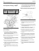
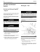
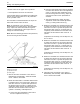
g00923080
Illustration 40
(1) Hole for crankshaft pin
(2) Hole for cam shaft pin
1. Remove the valve mechanism cover, the glow
plugs, and the cover for the front housing.
Note: Thecrankshafttimingpincanbeinsertedwith
the crankshaft pulley still on the engine.
2. Rotate the crankshaft in the normal direction of
theengineuntiltheinletvalveoftheNo.4cylinder
has just opened and the exhaust valve of the No.
4 cylinder has not completely closed.
3. Carefully rotate the crankshaft in the normal
direction of the engine in order to align the hole
in the crankshaft with the hole in the cylinder
block and the timing case. Insert the 27610211
Crankshaft Timing Pin fully into the hole in the
crankshaft web.
4. Insert the 27610212 Camshaft Timing Pin
through the hole in the camshaft gear and into the
body of the timing case. The engine is set at the
top center position for No. 1 piston.
Note: The camshaft gear can rotate a small amount
when the pin is installed.
5. Remove the timing pins from the camshaft gear
and the crankshaft web.