
User Manual

32 SENR9977
Testing and Adjusting Section
Testing and Adj
usting
Section
Fuel System
i02242712
Fuel System - Inspect
A number of the components that send fuel to
the engine can cause low fuel pressure. This can
decrease engine performance.
1. Check the fuel level in the fuel tank. Ensure that
the vent in the fuel cap is not filled with dirt.
2. Check all fuel lines for fuel leakage. The fuel lines
must be free from restrictions and faulty bends.
Verify that the fuel return line is not collapsed.
3. Inspect the fuel filter for excess contamination. If
necessary, install a new fuel filter. Determine the
source of the contamination. Make the necessary
repairs.
4. Service the primary fuel filter (if equipped).
5. Remove any air that may be in the fuel system.
Refer to Testing and Adjusting, “Fuel System -
Prime”.
i01854200
Air in Fu el - Test
This procedure checks for air in the fuel system. This
procedure also assists in finding the source of the air.
1. Examine the fuel system for leaks. Ensure that
the fuel line fittings are properly tightened. Check
the fuel level in the fuel tank. Air can enter the
fuel system on the suction side between the fuel
transfer pump and the fuel tank.
Work car
efully a round an engine that is running.
Engine parts that are hot, or parts that are moving,
can cause personal injury.
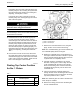
2. Install a suitable fuel flow tube with a visual sight
gauge in the fue
l return line. When possible, install
the sight gauge in a straight section of the fuel line
that is at least 304.8 mm (12 inches) long. Do not
install the si
ght gauge near the following devices
that create turbulence:
•
Elbows
•
Relief valves
•
Check valves
Observe the f
uel flow during engine cranking.
Look for air bubbles in the fuel. If there is no fuel
that is present in the sight gauge, prime the fuel
system. Refe
r to Testing and Adjusting, “Fuel
System - Prime” for more information. If the engine
starts, check for air in the fuel at varying engine
speeds. Whe
n possible, operate the engine under
the conditions which have been suspect.
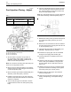
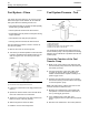
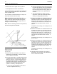
g00578151
Illustration 39
(1) A steady stream of s mall bubbles with a diam eter of
approximately 1.60 mm (0.063 inch) is an acceptable amount
of air in the fuel.
(2) Bubbles with a diameter of approximately 6.35 mm (0.250 inch)
are also acceptable if t here is two seconds to three seconds
intervals between b ubbles.
(3) Excessive air bubbles in the fuel a re not acc eptable.
3. If excessive air is seen in the sight gauge in the
fuel return line, install a second sight gauge at the
inlet to the fuel transfer pump. If a second sight
gauge is not available, move the sight gauge from
the fuel return line and install the sight gauge
at the inlet to the fuel transfer pump. Observe
the fuel flow during engine cranking. Look for air
bubbles in the fuel. If the engine starts, check for
air in the fuel at varying engine speeds.