
User Manual

SENR9977 11
Systems Operation Section
i02242521
Lubrication System
g01009682
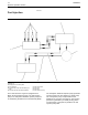
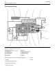
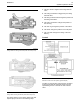
Illustration 7
Flow diagram of the lubrication system
Lubricating oil from the oil pan flows through a
strainer and a pipe (9) to the suction side of the
engine oil pump (10). Pressure for the lubrication
system is supplied by the oil pump. The crankshaft
gear (13) drives a lower idler gear (12). The lower
idler gear drives the oil pump gear (11). The pump
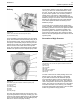
has an inner rotor and an outer rotor. The axis of
rotation of the rotors are off-center relative to each
other. There is an interference fit between the inner
rotor and the drive shaft.
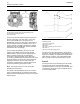
The inner rotor has five lobes which mesh with the six
lobes of the outer rotor. When the pump rotates, the
distance increases between the lobes of the outer
rotor and the lobes of the inner rotor in order to create
suction. When the distance decreases between the
lobes, pressure is created.
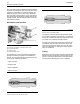
The lubricating oil flows from the outlet side of the oil
pump (10) through a passage to the oil filter head
(7). The oil then flows from the oil filter head through
a passage to a plate type oil cooler. The oil cooler is
located on the left side of the cylinder block.
From the oil cooler, the oil returns through a passage
to the oil filter head. The oil then flows through a
bypass valve that permits the lubrication system
to function if the oil filter becomes blocked. Under
normal conditions, the oil then flows to the oil filter (8).
The oil flows from the oil filter through a passage that
is drilled across the cylinder block to the oil gallery
(4). The oil gallery is drilled through the total length
of the left side of the cylinder block. If the oil filter is
on the right side of the engine, the oil flows through
a passage that is drilled across the cylinder block to
the pressure g allery.