SENR9977 February 2005 Systems Operation Testing and Adjusting 1104E Engine RF11-Up (Machine) RH11-Up (Machine) RK11-Up (Machine)
i01658146 Important Safety Information Most accidents that involve product operation, maintenance and repair are caused by failure to observe basic safety rules or precautions. An accident can often be avoided by recognizing potentially hazardous situations before an accident occurs. A person must be alert to potential hazards. This person should also have the necessary training, skills and tools to perform these functions properly.
SENR9977 3 Table of Contents Table of Contents Flywheel Housing - Inspect ................................... 54 Gear Group - Inspect ............................................ 55 Systems Operation Section Electrical System Alternator - Test .................................................... Battery - Test ......................................................... V-Belt - Test .......................................................... Charging System - Test ........................................
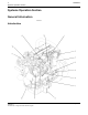
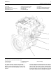
Systems Operation Section SENR9977 Systems Operation Section General Information i02245816 Introduction Illustration 1 Left side view of a typical 1104C electronic engine g01130896
SENR9977 (1) Fuel lines (2) Fuel Priming Pump (3) Fuel Filter (4) Machine Interface Connector (MIC) (5) Speed/timing sensor 5 Systems Operation Section (6) Electronic fuel injection pump (7) Engine oil pressure sensor (8) Engine oil filter (9) Water Pump (10) Crankshaft pulley (11) Alternator (12) Engine coolant temperature sensor (13) Voltage Load Protection Module (14) Electronic Control Module (ECM) g01131299 Illustration 2 Right side view of a typical 1104C electronic engine (15) Exhaust elbow (16
Systems Operation Section SENR9977 Each cylinder has a piston cooling jet that is installed in the cylinder block. The piston cooling jet sprays engine oil onto the inner surface of the piston in order to cool the piston. The pistons have a Fastram combustion chamber in the top of the piston in order to provide an efficient mix of fuel and air. The piston pin is off-center in order to reduce the noise level. The pistons have two compression rings and an oil control ring.
SENR9977 7 Systems Operation Section The engine has a cast iron cylinder head. The inlet manifold is integral within the cylinder head. An inlet valve and an exhaust valve for each cylinder are controlled by a pushrod valve system. The ports for the inlet valves are on the left side of the cylinder head. The ports for the exhaust valves are on the right side of the cylinder head.
Systems Operation Section Engines which are naturally aspirated pull outside air through an air cleaner directly into the inlet manifold (6). The air flows from the intake manifold to the engine cylinders (7). The fuel is mixed with the air in the engine cylinders. After the fuel combustion occurs in the engine cylinder, the exhaust gases flow directly to the outside air through the exhaust manifold (8).
SENR9977 The turbine wheel and the compressor wheel (3) are installed on the same shaft. Therefore, the turbine wheel and the compressor wheel rotate at the same rpm. The compressor wheel is enclosed by the compressor housing (2). The compressor wheel compresses the intake air (1). The intake air flows into the engine cylinders through the inlet valves of the cylinders.
Systems Operation Section SENR9977 i02242619 Cooling System Illustration 6 g00985481 Flow diagram of the cooling system The coolant flows from the bottom of the radiator to the centrifugal water pump. The water pump assists in the flow of the coolant through the system. The water pump is installed on the front of the timing case. The water pump is gear-driven by the fuel injection pump gear.
SENR9977 11 Systems Operation Section i02242521 Lubrication System Illustration 7 g01009682 Flow diagram of the lubrication system Lubricating oil from the oil pan flows through a strainer and a pipe (9) to the suction side of the engine oil pump (10). Pressure for the lubrication system is supplied by the oil pump. The crankshaft gear (13) drives a lower idler gear (12). The lower idler gear drives the oil pump gear (11). The pump has an inner rotor and an outer rotor.
Systems Operation Section SENR9977 Lubricating oil from the oil gallery flows through high pressure passages to the main bearings of the crankshaft (5). Then, the oil flows through the passages in the crankshaft to the connecting rod bearing journals (6). The pistons and the cylinder bores are lubricated by the splash of oil and the oil mist. Alternator Lubricating oil from the main bearings flows through passages in the cylinder block to the journals of the camshaft.
SENR9977 13 Systems Operation Section The alternator is connected to the battery through the ignition switch. Therefore, alternator excitation occurs when the switch is in the ON position. Starting Motor g00956095 Illustration 9 24 Volt Starting Motor (1) Terminal for connection of the ignition switch (2) Terminal for connection of the battery cable The starting motor has a solenoid.
Systems Operation Section SENR9977 i02247913 Fuel Injection g01131813 Illustration 11 Flow diagram of the fuel system (1) Fuel injectors (2) Fuel transfer pump and secondary fuel filter (3) Primary fuel filter and water separator (4) (5) (6) (7) Fuel return lines Fuel lines Fuel tank Fuel injection pump The 1104C electronic engine is equipped with a Bosch VP30 fuel injection pump.
SENR9977 When the engine is operated, the fuel is pulled from the fuel tank (6) through the primary fuel filter/water separator (3) by the fuel transfer pump (2). When the fuel passes through the water separator, any water in the fuel will go to the bottom of the bowl. The fuel transfer pump is equipped with a secondary fuel filter. From the fuel priming pump, the fuel passes through the fuel supply line to the fuel injection pump (7).
Systems Operation Section SENR9977 Fuel Injection Pump g01132091 Illustration 12 Schematic of the Bosch VP30 fuel injection pump (1) Speed/timing sensor (2) Electronic control unit (ECU) for the fuel injection pump (3) Fuel transfer pump (4) Fuel solenoid valve (5) Distributor plunger (6) Fuel injector (7) Delivery valve (8) Cam plate (9) Roller (10) Timing advance mechanism (11) Timing solenoid valve (12) Fuel transfer pump (13) Pressure regulator (14) ECM (15) Cam ring The fuel injection pump has
SENR9977 17 Systems Operation Section Delivery Illustration 13 The eccentric position of the rotor is relative to the cam ring. A volume is created between the vanes, the rotor, and the cam ring. The fuel is transported by the eccentric position. The eccentric position is relative to the rotor and the outlet passage (19). The fuel is transferred to the outlet passage into the distributor plunger. The volume of the fuel is reduced between the inlet passage and the outlet passage.
Systems Operation Section SENR9977 The cam plate moves the distributor plunger toward the head of the distributor (26). The high pressure is created by a decrease in the volume between the distributor plunger and the head of the distributor. The cam plate is pressed to the ring by two springs (28). This brings the distributor plunger back to the original position. The fuel solenoid valve closes the high pressure volume.
SENR9977 19 Systems Operation Section 1. The ECU sends a signal to the timing solenoid valve. 2. The timing mechanism is triggered by the timing solenoid valve. 3. The timing solenoid valve changes the pressure in the timing mechanism. 4. The timing mechanism changes the position of the cam ring. 5. The cam ring changes the position of the rollers. 6. The rollers change the position of the cam plate. 7. The cam plate changes the timing of the fuel delivery.
Systems Operation Section Illustration 22 SENR9977 g01133212 The timing wheel and the secondary speed/timing sensor (32) Secondary speed/timing sensor (33) Timing wheel The ECU for the fuel injection pump is mounted on the top of the pump. The ECU has a connection to the engine ECM and a connection to the speed/timing sensor. The ECU has a connection for the two solenoid valves. The ECM functions as a control computer. The ECU calculates the optimal parameters from the ECM data.
SENR9977 21 Systems Operation Section Fuel Injectors Illustration 24 g01142467 Each fuel injector is held into the cylinder head by a clamp around the fuel injector. The fuel injectors are not serviceable but the nozzles can be removed in order to clean the orifice. The fuel injection pump forces the fuel to flow under high pressure to the hole in the fuel inlet. The fuel then flows around a needle valve within the nozzle holder which causes the nozzle to fill with fuel.
Systems Operation Section SENR9977 i02251280 Electronic Control System g01133227 Illustration 25 Schematic of the electronic control system (1) Voltage load-dump protection module (VLPM) (2) Service tool connector (3) Machine interface connector (4) ECM (5) Coolant temperature sensor (6) Intake manifold temperature sensor (7) Engine oil pressure sensor The electronic control system for the 1104C electronic engine has the following components: • Electronic control module (ECM) • Pressure sensors •
SENR9977 23 Systems Operation Section Electronic Control Module (ECM) Flash programming is the method of programming or updating the personality module. Refer to Troubleshooting, RENR2696, “Flash Programming ” for the instructions on the flash programming of the personality module. The ECM is sealed and the ECM needs no routine adjustment or maintenance. Pressure Sensors Illustration 26 g01133234 Electronic control module (ECM) The ECM functions as the governor and the computer for the fuel system.
Systems Operation Section SENR9977 The engine oil pressure sensor is also an active sensor with three wires and a power supply. The sensor provides the ECM with a measurement of engine oil pressure. The ECM can warn the operator of possible conditions that can damage the engine. This includes the detection of a blocked oil filter. Primary Speed/Timing Sensor The operating range for the engine oil pressure sensor ....................... 110 to 882 kPa (16 to 128 psi) Required accuracy .........
SENR9977 25 Systems Operation Section Voltage Load-dump Protection Module (VLPM) Illustration 31 g01133354 (1) VLPM The VLPM monitors the voltage of the system and the VLPM will protect the ECU on the fuel injection pump against voltage spikes and reverse polarity. The fuel injection pump will be shutdown if there is high voltage on the system.
Systems Operation Section SENR9977 ECM Power Supply Illustration 32 g01141374 Power Supply for the ECM The power supply to the ECM and the system is drawn from the 24 volt or the 12 volt battery. The power supply for the ECM has the following components: • Battery • disconnect switch • Key start switch • Fuses • Ground bolt • ECM connector • Machine interface connector Note: The ground bolt is the only component that is mounted on the engine.
SENR9977 27 Systems Operation Section Power Supply for the Fuel Injection Pump g01141661 Illustration 33 Power supply for the fuel injection pump Illustration 34 Connection for the fuel injection pump (J40/P40) g00931447 Illustration 35 g01143327 Connector for the fuel injection pump (J40) (1) (2) (3) (4) (5) (6) (7) (8) (9) Can Can + Unused Unused Fuel shutoff Battery Battery + Signal for primary speed/timing sensor Unused The power supply for the ECM comes from the machine interface connector.
Systems Operation Section SENR9977 Power Supply for the Pressure Sensors Illustration 36 g01143335 Schematic for pressure sensors The ECM supplies 5.0 ± 0.2 DC volts through the ECM connector to each sensor. The power supply is protected against short circuits. A short in a sensor or a wiring harness will not cause damage to the ECM. Power Supply for the Throttle Position Sensor Illustration 37 Schematic for the throttle position sensor The ECM supplies 8.0 ± 0.
SENR9977 29 Systems Operation Section i02285310 Glossary of Electronic Control Terms Diagnostic Lamp – A diagnostic lamp is sometimes called the check engine light. The diagnostic lamp is used to warn the operator of the presence of an active diagnostic code. Direct Current (DC) – Direct current is the type of current that flows consistently in only one direction. Aftermarket Device – An aftermarket device is a device or an accessory that is installed by the customer after the engine is delivered.
Systems Operation Section SENR9977 Open Circuit – An open circuit is a broken electrical wire connection. The signal or the supply voltage cannot reach the intended destination. Original Equipment Manufacturer (OEM) – An OEM is the manufacturer of a vehicle that utilizes a Perkins engine. Parameter – A parameter is a programmable value which affects the characteristics or the behavior of the engine and/or vehicle.
SENR9977 Supply Voltage – Supply voltage is a constant voltage that is supplied to a component in order to provide electrical power for operation. Supply voltage may be generated by the ECM. Supply voltage may also be the battery voltage of the vehicle that is supplied by the vehicle wiring. “T” Harness – This harness is a test harness that is designed to permit normal circuit operation and the measurement of the voltage simultaneously.
Testing and Adjusting Section SENR9977 Testing and Adjusting Section 2. Install a suitable fuel flow tube with a visual sight gauge in the fuel return line. When possible, install the sight gauge in a straight section of the fuel line that is at least 304.8 mm (12 inches) long.
SENR9977 33 Testing and Adjusting Section If excessive air is not seen at the inlet to the fuel transfer pump, the air is entering the system after the fuel transfer pump. Refer to the Testing and Adjusting, “Fuel System - Prime”. If excessive air is seen at the inlet to the fuel transfer pump, air is entering through the suction side of the fuel system. To avoid personal injury, always wear eye and face protection when using pressurized air.
Testing and Adjusting Section SENR9977 Fuel Injection Timing - Adjust 6. Insert the 27610032 Timing Pin through the hole in the fuel pump gear and through the slot in the hub. Push the timing pin fully into the hole in the body of the fuel injection pump. Table 2 Note: The 27610032 Timing Pin must be a sliding fit in the hole in the body of the fuel injection pump. i02285307 Required Tools Part Number 27610032 Part Description Timing Pin Qty 1 Illustration 42 g01143217 7.
SENR9977 35 Testing and Adjusting Section i02253244 Fuel Injection Timing - Check 4. Remove all three timing pins and install the removed components. i02243111 Fuel Quality - Test Table 3 Required Tools Part Number 27610032 Part Description Timing Pin Qty 1 1. Set the number one piston at top center on the compression stroke. Refer to Testing and Adjusting, “Finding Top Center Position for No. 1 Piston” for the correct procedure.
Testing and Adjusting Section SENR9977 i02253606 Fuel System - Prime i02253617 Fuel System Pressure - Test If air enters the fuel system, the air must be purged before the engine can be started. Air can enter the fuel system when the following events occur: • The fuel tank is empty or the tank has been partially drained during normal operation. • The low pressure fuel lines are disconnected. • A leak exists in the low pressure fuel system during engine operation.
SENR9977 7. Start the engine and check for any leakage of fuel or air from the fuel lines. Check the Function of the Pressure Regulator 1. Remove the fuel line from the outlet for the supply for the fuel injection pump (3). 2. Install a pipe with a tap for a pressure gauge. Connect a 0 to 80 kPa (0 to 12 psi) pressure gauge. 3. Start the engine and run the engine at idle for two minutes in order to remove any trapped air. 4. Record the pressure reading at idle and at rated speed.
Testing and Adjusting Section SENR9977 Air Inlet and Exhaust System i02254115 Wastegate - Test i02253770 Air Inlet and Exhaust System - Inspect A general visual inspection should be made to the air inlet and exhaust system. Make sure that there are no signs of leaks in the system. There will be a reduction in the performance of the engine if there is a restriction in the air inlet system or the exhaust system. Hot engine components can cause injury from burns.
SENR9977 39 Testing and Adjusting Section 3. Slowly apply air pressure to the wastegate so that the actuator rod moves 1.0 mm (0.039 inch). The air pressure should be within 107 to 117 kPa (15.5 to 17.0 psi). Ensure that the dial indicator returns to zero when the air pressure is released. Repeat the test several times. This will ensure that an accurate reading is obtained. 4. For more information on installing a new turbocharger, contact your Perkins dealer or your Perkins distributor.
Testing and Adjusting Section SENR9977 • Broken socket on the upper end of a pushrod • Loose adjustment screw for the valve lash If the camshaft and the valve lifters show rapid wear, look for fuel in the lubrication oil or dirty lubrication oil as a possible cause. The valve lash is measured between the top of the valve stem and the rocker arm lever. Note: An adjustment is not necessary if the measurement of the valve lash is in the acceptable range. Inspect the valve lash while the engine is stopped.
SENR9977 41 Testing and Adjusting Section i01889422 Valve Depth - Inspect Table 4 3. Inspect the valves for cracks and other damage. Check the valve stems for wear. Check that the valve springs are the correct length under the test force. Refer to Specifications, “Cylinder Head Valves” for the dimensions and tolerances of the valves and the valve springs.
Testing and Adjusting Section 5. Move the valve in a radial direction toward the dial indicator as far as possible. Note the distance of movement which is indicated on the dial indicator. If the distance is greater than the maximum clearance of the valve in the valve guide, replace the valve guide. When new valve guides are installed, new valves and new valve seat inserts must be installed. Valve guides and valve seat inserts are supplied as an unfinished part.
SENR9977 43 Testing and Adjusting Section Lubrication System Perform the following procedures in order to inspect the oil pump for clearances and torques. i01854908 Engine Oil Pressure - Test Refer to the Specifications Module, “Engine Oil Pump”. 1. Remove the oil pump from the engine. Refer to the Disassembly and Assembly, “Engine Oil Pump - Remove”. Remove the cover of the oil pump. Low Oil Pressure The following conditions will cause low oil pressure. 2. Remove the outer rotor.
Testing and Adjusting Section SENR9977 i01126690 Excessive Bearing Wear Inspect When some components of the engine show bearing wear in a short time, the cause can be a restriction in an oil passage. An engine oil pressure indicator may show that there is enough oil pressure, but a component is worn due to a lack of lubrication. In such a case, look at the passage for the oil supply to the component. A restriction in an oil supply passage will not allow enough lubrication to reach a component.
SENR9977 45 Testing and Adjusting Section • Overfilling of the crankcase • Wrong dipstick or guide tube • Sustained operation at light loads Excessive consumption of engine oil can also result if engine oil with the wrong viscosity is used. Engine oil with a thin viscosity can be caused by fuel leakage into the crankcase or by increased engine temperature. i01945015 Increased Engine Oil Temperature - Inspect Look for a restriction in the oil passages of the oil cooler (if equipped).
Testing and Adjusting Section SENR9977 Cooling System 8. Check the filler cap. A pressure drop in the cooling system can cause the boiling point to be lower. This can cause the cooling system to boil. Refer to Testing and Adjusting, “Cooling System - Test”. i02274237 Cooling System - Check (Overheating) Above normal coolant temperatures can be caused by many conditions. Use the following procedure to determine the cause of above normal coolant temperatures: 1.
SENR9977 47 Testing and Adjusting Section i01889427 i01964006 Cooling System - Inspect Cooling System - Test This engine has a pressure type cooling system. A pressure type cooling system gives two advantages: Remember that temperature and pressure work together. When a diagnosis is made of a cooling system problem, temperature and pressure must be checked. The cooling system pressure will have an effect on the cooling system temperature. For an example, refer to Illustration 53.
Testing and Adjusting Section SENR9977 Checking the Filler Cap One cause for a pressure loss in the cooling system can be a faulty seal on the radiator pressure cap. Remove any deposits that are found on these items, and remove any material that is found on these items. 3. Install the pressure cap onto a suitable pressurizing Pump. 4. Observe the exact pressure that opens the filler cap. 5. Compare the pressure to the pressure rating that is found on the top of the filler cap. 6.
SENR9977 49 Testing and Adjusting Section • The dial indicator remains constant beyond five minutes. The inside of the cooling system has leakage only if the following conditions exist: • The reading on the gauge goes down. • You do NOT observe any outside leakage. Make any repairs, as required. i02265391 5. Refer to Disassembly and Assembly, “Engine Oil Cooler - Install” for installation of the engine oil cooler. 6.
Testing and Adjusting Section SENR9977 Basic Engine i01889476 Piston Ring Groove - Inspect Note: Some pistons have a tapered top groove and the piston ring is wedged. The clearance for the top piston ring cannot be checked by the above method when this occurs. Inspect the Piston Ring End Gap Inspect the Piston and the Piston Rings 1. Check the piston for wear and other damage. 2. Check that the piston rings are free to move in the grooves and that the rings are not broken.
SENR9977 51 Testing and Adjusting Section i01748770 Connecting Rod Bearings Inspect Check the connecting rod bearings and the connecting rod bearing journal for wear or other damage. Connecting rod bearings are available with a smaller inside diameter than the original size bearings. These bearings are for crankshafts that have been ground. Illustration 57 g00927038 Inspection of the connecting rod parallel alignment.
Testing and Adjusting Section SENR9977 i01905914 Cylinder Head - Inspect Refer to Specifications, “Cylinder Head” for the requirements of flatness. Remachining the Cylinder Head 1. Remove the cylinder head from the engine. 2. Remove the water temperature regulator housing. 3. Inspect the cylinder head for signs of gas or coolant leakage.
SENR9977 53 Testing and Adjusting Section The correct piston height must be maintained in order to ensure that the engine conforms to the standards for emissions. Note: The top of the piston should not be machined. If the original piston is installed, be sure that the original piston is assembled to the correct connecting rod and installed in the original cylinder.
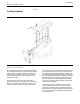
Testing and Adjusting Section SENR9977 Flywheel Runout Illustration 62 g00913387 g00987752 Illustration 61 1. Install the dial indicator. Refer to Illustration 61. 1. Install the 21825617 dial gauge. See Illustration 62. 2. Set the pointer of the dial indicator to 0 mm (0 inch). 2. Set the pointer of the 21825617 dial gauge to 0 mm (0 inch). 3. Turn the flywheel. Read the dial indicator for every 90 degrees. 3. Check the concentricity at intervals of 90 degrees around the flywheel housing.
SENR9977 55 Testing and Adjusting Section i02270822 Gear Group - Inspect Illustration 64 Illustration 63 g00913389 1. Install the 21825617 dial gauge. See Illustration 63. 2. Set the pointer of the 21825617 dial gauge to 0 mm (0 inch). 3. Check the alignment at intervals of 90 degrees around the flywheel housing. 4. Calculate the difference between the lowest measurement and the highest measurement. This difference must not be greater than the limit that is given in Table 7.
Testing and Adjusting Section SENR9977 Electrical System i01899123 Alternator - Test 4. Turn the ignition switch to the ON position. Check the voltage between terminal (B) and ground. If the voltage is more than 2 Volts the alternator needs to be replaced. Warning Light is On When the Engine is Running 1. Start the engine and run the engine at fast idle. 2. Measure the voltage between terminal (A) and ground. 3. Measure the voltage between terminal (B) and ground. 4.
SENR9977 57 Testing and Adjusting Section Never disconnect any charging unit circuit or battery circuit cable from the battery when the charging unit is operated. A spark can cause an explosion from the flammable vapor mixture of hydrogen and oxygen that is released from the electrolyte through the battery outlets. Injury to personnel can be the result. The battery circuit is an electrical load on the charging unit. The load is variable because of the condition of the charge in the battery.
Testing and Adjusting Section SENR9977 When it is possible, make a test of the charging unit and voltage regulator on the engine, and use wiring and components that are a permanent part of the system. Off-engine testing or bench testing will give a test of the charging unit and voltage regulator operation. This testing will give an indication of needed repair. After repairs are made, perform a test in order to prove that the units have been repaired to the original condition of operation.
SENR9977 59 Testing and Adjusting Section Voltage drops that are greater than the amounts in Table 10 are caused most often by the following conditions: • The voltage at the battery post is within 2 volts • Loose connections • The large starting motor cables get hot. • Corroded connections Use a suitable ammeter in order to measure the current. Place the jaws of the ammeter around the cable that is connected to the “bat” terminal.
Testing and Adjusting Section SENR9977 5. Rotate the crankshaft by hand in order to ensure that the crankshaft is not stuck. Check the oil viscosity and any external loads that could affect the engine rotation. a. If the crankshaft is stuck or difficult to turn, repair the engine. b. If the engine is not difficult to turn, go to Step 6. 3. Place a suitable ammeter on the power supply wire. 4. Connect a suitable digital multimeter to the terminal on the glow plug and to a suitable ground. 5.
SENR9977 61 Index Section Index A Air in Fuel - Test..................................................... 32 Air Inlet and Exhaust System ............................ 7, 38 Cylinder Head And Valves ................................... 9 Turbocharger ....................................................... 8 Air Inlet and Exhaust System - Inspect.................. 38 Alternator - Test ..................................................... 56 Warning Lamp Does Not Illuminate ...................
Index Section SENR9977 M Main Bearings - Inspect......................................... 51 P Piston Height - Inspect .......................................... Piston Ring Groove - Inspect................................. Inspect the Clearance of the Piston Ring........... Inspect the Piston and the Piston Rings ............ Inspect the Piston Ring End Gap....................... Power Sources ...................................................... ECM Power Supply......................................
SENR9977 63 Index Section
©2005 Perkins Engines Company Limited All Rights Reserved Printed in U.K.