
User Manual
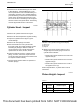

Alternator output should be 28 ± 1 V on a 24 V
system and 14 ± 0.5 V on a 12 V system. No
adjustment can be made in order to change the rate
of charge on the alternator regulators. If the rate of
charge is not correct, a replacement of the regulator
is necessary. For individual alternator output, refer to
Specifications, “Alternator”.
i04371153
V-Belt - Test
NOTICE
Ensure that the engine is stopped before any servic-
ing or repair is performed.
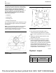
To maximize the engine performance, inspect the
poly v-belt for wear and for cracking. Replace the
poly v-belt if the belt is worn or damaged.
• Check the poly v-belt for cracks, splits, glazing,
grease, displacement of the cord and evidence of
fluid contamination.
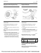
The poly v-belt must be replaced if the following
conditions are present.
• The poly v-belt has a crack in more than one rib.
• More than one section of the poly v-belt is
displaced in one rib of a maximum length of
50.8 mm (2 inch).
To replace the poly v-belt, refer to Operation and
Maintenance Manual, “Alternator and Fan Belts -
Replace”.
i03923009
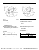
Electric Starting System - Test
General Information
Power which is available during cranking varies
according to the temperature and condition of the
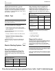
batteries. Table 14 shows the voltages which are
expected from a battery at the various temperature
ranges.
Table 14
Typical Voltage Of Electrical System During Cranking At Vari-
ous Ambient Temperatures
Temperature 12 V System 24 V System
−23 to −7°C
(−10 to 20°F)
6 to 8 V 12 to 16 V
−7 to 10°C (20 to 50°F) 7 to 9 V 14 to 18 V
10 to 27°C (50 to 80°F) 8 to 10 V 16 to 24 V
Table 15 shows the maximum acceptable loss of
voltage in the battery circuit. The battery circuit
supplies high current to the starting motor. The
values in the table are for engines which have service
of 2000 hours or more. The voltage drop for new
machines is less than the voltage shown in table 15 .
Table 15
Maximum Acceptable Voltage Drop In The Starting Motor Cir-
cuit During Cranking
Circuit 12 V System 24 V System
Battery post “-” to the
starting motor terminal “-”
0.7 V 1.4 V
Drop across the discon-
nect switch
0.5 V 1.0 V
Battery post “+” to the ter-
minal of the starting mo-
tor solenoid “+”
8 to 10 V 16 to 20 V
Solenoid terminal “Bat” to
the solenoid terminal
“Mtr”
0.4 V 0.8 V
Voltage drops that are greater than the amounts in
table 15 are caused most often by the following
conditions:
• Loose connections
• Corroded connections
• Faulty switch contacts
Diagnosis Procedures
The procedures for diagnosing the starting motor are
intended to help the technician determine if a starting
motor needs to be replaced or repaired. The
procedures are not intended to cover all possible
problems and conditions. The procedures serve only
as a guide.
NOTICE
If equipped with electric start, do not crank the engine
for more than 30 seconds. Allow the starter to cool for
two minutes before cranking again.
Never turn the disconnect switch off while the engine
is running. Serious damage to the electrical system
can result.
90 UENR0623-02
Electrical System
This document has been printed from SPI2. NOT FOR RESALE