
User Manual

d. Turn the disconnect switch to the ON position.
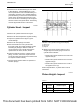
Connect an ammeter across the disconnect
switch terminals. Connect the red lead to the
terminal on the frame side. Connect the black
lead to the terminal on the battery. If a
multimeter is used for the test use the ten amp
connections to avoid damage.
e. Turn the disconnect switch to the OFF position.
Record the value of the electrical current.
f. The current is below 0.05 amperes. The
charging system is currently good. The fault is
possibly an intermittent draw in the system. The
batteries may be faulty. Check that no
accessories were on during the test.
Note: The standard acceptable draw is 0.05
amperes. A current that is greater than this value
usually indicates a problem. However, some large
machines with multiple control modules have a
higher acceptable limit.
g. The current value is above 0.05 amperes. There
is a current draw in the system. Go to step 7.
5. Turn off all accessories. Turn the keyswitch to the
OFF position.
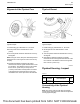
a. Connect a current probe or an ammeter to a
digital multimeter. Ensure that the probe is
zeroed. Clamp the current probe or an ammeter
around the ground cable. Clamp the tool with
the positive side away from the battery. Record
the value of the electrical current.
b. The current value is below 2 amperes. Go to
step 4.d.
c. The current value is above 2 amperes. Go to
step 7.
d. Remove the ground cable from the battery
terminal. For systems with four batteries or 12 V
systems with two batteries, disconnect the
ground cables from both negative batteries.
e. Connect an ammeter between the disconnected
battery ground cable and one of the negative
battery terminals. Connect the red lead to the
cable. Connect the black lead to the terminal on
the battery. If a multimeter is used for the test
use the ten amp connections to avoid damage.
f. The current is below 0.05 amperes. The
charging system is currently good. The fault is
possibly an intermittent draw in the system. The
batteries may be faulty. Check that no
accessories were on during the test.
Note: The standard acceptable draw is 0.05
amperes. A current value above this figure usually
indicates a problem. However, some large
machines with multiple control modules have a
higher acceptable limit.
g. The current value is above 0.05 amperes. There
is a current draw in the system. Go to step 7.
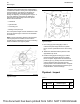
6. Check the condition of the poly v-belt and
alternator pulley.
a. If the poly v-belt is oily, clean the pulleys.
Replace the poly v-belt. Refer to Disassembly
and Assembly, “Alternator Belt - Remove and
Install” for the correct procedure. Inspect the
poly v-belt for wear or for cracks. Refer to
Systems Operation, Testing and Adjusting, “V-
Belt - Test”. If the poly v-belt is wet, dry the poly
v-belt and the pulleys. Retest the system.
b. Inspect the nut on the alternator pulley. Ensure
that the nut is not loose. If the nut is loose,
tighten the nut to the correct torque. Refer to
Specifications, “Alternator” for the correct
torque.
c. If no faults are found from the procedures in
step 6.a and step 6.b, inspect the charging
system. Refer to Systems Operation, Testing
and Adjusting, “Charging System - Test” for the
correct procedure.
7. Turn the keyswitch to the OFF position.
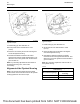
a. Connect a current probe or an ammeter to a
digital multimeter. Ensure that the probe is
zeroed. Clamp the current probe or an ammeter
around the “B+” cable. Clamp the tool with the
positive side away from the battery. Record the
value of the electrical current.
b. The current is less than two amperes. Go to
step 7.d.
c. The current is more than two amperes. There is
an internal problem with the alternator. Replace
the alternator. Refer to Disassembly and
Assembly, “Alternator - Remove and Install” for
the correct procedure.
d. Disconnect the wire for “B+” terminal from the
alternator. Connect the red lead of the
multimeter to the wire for the “B+” terminal.
Connect the black lead of the multimeter to the
“B+” terminal on the alternator. Set the
multimeter to ten amp. Record the value of the
electrical current.
88 UENR0623-02
Electrical System
This document has been printed from SPI2. NOT FOR RESALE