
User Manual

i04175270
Gear Group - Inspect
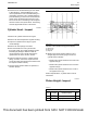
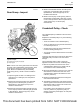
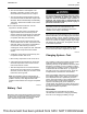
Illustration 76 g02859779
Typical example
(3) Accessory drive gear (if equipped)
(7) Oil pump gear
Note: If one or more of the gears need to be removed
for repair, refer to Disassembly and Assembly, “Gear
Group (Front) - Remove” in order to remove the
gears. Refer to the Disassembly and Assembly,
“Gear Group (Front) - Install” in order to install the
gears.
1. Inspect the gears for wear or for damage. If the
gears are worn or damaged, use new parts for
replacement.
2. Measure the clearance between the crankshaft
gear (5) and the camshaft gear (4). Refer to
Specifications, “Gear Group (Front)” for the
clearance measurement.
3. Measure the clearance between the idler gear (6)
for the oil pump and the crankshaft gear (5). Refer
to Specifications, “Gear Group (Front)” for the
clearance measurement.
4. Measure the backlash between the fuel injection
pump gear (1) and the idler gear (2). Refer to
Specifications, “Gear Group (Front)” for the
backlash measurement.
5. Measure the end play on idler gear (2). Refer to
Disassembly and Assembly, “Idler Gear - Install”
for the correct procedure. Refer to Specifications,
“Gear Group (Front)” for the end play
measurement.
i04338214
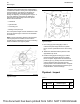
Crankshaft Pulley - Check
The crankshaft pulley is installed on the front of the
crankshaft.
Replace the crankshaft pulley if any of the following
conditions exist:
• There is movement of the crankshaft pulley.
• There is a large amount of gear train wear that is
not caused by lack of oil.
• Analysis of the engine oil has revealed that the
front main bearing is badly worn.
• The engine has had a failure because of a broken
crankshaft.
Check the areas around the holes for the bolts in the
crankshaft pulley for cracks or for wear and for
damage.
Use the following steps in order to check the
alignment and the runout of the crankshaft pulley:
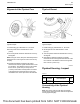
1. Remove any debris from the front face of the
crankshaft pulley. Remove any debris from the
circumference of the crankshaft pulley.
2. Mount the dial indicator on the front cover. Use the
dial indicator to measure the outer face of the
crankshaft pulley. Set the dial indicator to read
0.00 mm (
0.00
inch).
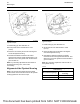
3. Rotate the crankshaft at intervals of 45 degrees
and read the dial indicator.
4. The difference between the lower measurements
and the higher measurements that are read on the
dial indicator at all four points must not be more
than 0.18 mm (0.007 inch).
If the reading on the dial indicator is more than
0.18 mm (0.007 inch), inspect the pulley for
damage. If the pulley is damaged, use new parts
for replacement.
UENR0623-02 85
Basic Engine
This document has been printed from SPI2. NOT FOR RESALE