
User Manual
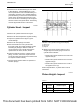
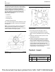
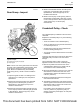
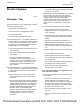
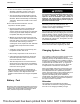
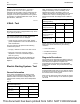

Illustration 74 g01199468
Typical example
1. Install Tooling (A). See illustration 74 .
2. Set the pointer of the dial indicator to 0 mm
(0 inch).
3. Check the concentricity at intervals of 45 degrees
around the flywheel housing.
4. Calculate the difference between the lowest
measurement and the highest measurement. This
difference must not be greater than the limit that is
given in Table 13 .
Note: Any necessary adjustment must be made on
the flywheel housing. Then, recheck the
concentricity.
Alignment of the Flywheel Housing
Note: This check must be made with the flywheel
and the starter removed and the bolts for the flywheel
housing tightened to the correct torque.
Illustration 75 g01199467
Typical example
1. Install Tooling (A). See illustration 75 .
2. Set the pointer of the dial indicator to 0 mm
(0 inch).
3. Check the alignment at intervals of 45 degrees
around the flywheel housing.
4. Calculate the difference between the lowest
measurement and the highest measurement. This
difference must not be greater than the limit that is
given in Table 13 .
Note: Any necessary adjustment must be made on
the flywheel housing.
Table 13
Limits for Flywheel Housing Runout and Alignment (Total In-
dicator Reading)
Bore of the Housing Flange
Maximum Limit (Total Indica-
tor Reading)
410 mm (16.14 inch) 0.25 mm (0.010 inch)
448 mm (17.63 inch) 0.28 mm (0.011 inch)
84 UENR0623-02
Basic Engine
This document has been printed from SPI2. NOT FOR RESALE