
User Manual


Alignment of the Flywheel Face
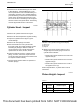
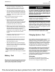
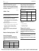
Illustration 72 g01332565
Typical example
1. Install Tooling (A) in illustration 72 , as shown.
2. Set the pointer of the dial indicator to 0 mm
(0 inch).
3. Turn the flywheel. Read the dial indicator for every
45 degrees.
Note: During the check, keep the crankshaft pressed
toward the front of the engine in order to remove any
end play.
4. Calculate the difference between the lowest
measurement and the highest measurement of the
four locations. This difference must not be greater
than 0.03 mm (0.001 inch) for every 25 mm
(1.0 inch) of the radius of the flywheel. The radius
of the flywheel is measured from the axis of the
crankshaft to the contact point of the dial indicator.
Flywheel Runout
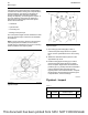
Illustration 73 g01321858
Typical example
1. Install Tooling (A) in illustration 73 , as shown.
2. Set the pointer of the dial indicator to 0 mm
(0 inch).
3. Turn the flywheel. Read the dial indicator for every
45 degrees.
4. Calculate the difference between the lowest
measurement and the highest measurement of the
four locations. This difference must not be greater
than 0.30 mm (0.012 inch).
i02406200
Flywheel Housing - Inspect
Table 12
Required Tools
Tool
Part
Number
Part Description Qty
A
21825617
Dial Gauge 1
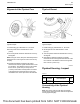
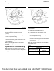
Concentricity of the Flywheel
Housing
Note: This check must be made with the flywheel
and the starter removed and the bolts for the flywheel
housing tightened lightly.
UENR0623-02 83
Basic Engine
This document has been printed from SPI2. NOT FOR RESALE