
User Manual

Basic Engine
i04823065
Position the Valve Mechanism
Before Maintenance
Procedures
NOTICE
Ensure that this procedure is carried out before
the rocker shaft is removed.
Table 9
Required Tools
Tool Part Number
Part Description Qty
A
(1)
27610291
Barring Device Housing
1
27610289 Gear 1
(1)
This Tool is used in the aperture for the electric starting motor.
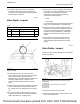
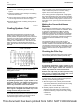
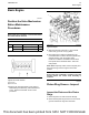
Illustration 65 g01353215
Cylinder and valve location
(A) Inlet valve
(B) Exhaust valve
1. Remove the valve mechanism cover. Refer to
Disassembly and Assembly, “Valve Mechanism
Cover - Remove and Install” for the correct
procedure.
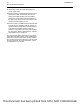
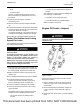
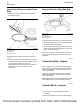
Illustration 66 g02948536
Typical example
2. Select an exhaust rocker arm (1). The exhaust
rocker arm (1) can be on any cylinder.
3. Use Tooling (A) to rotate the crankshaft in the
normal direction of rotation until the hydraulic lash
adjuster starts to open the exhaust valve.
Continue to rotate the crankshaft until the valve
has opened to the maximum extent. This is the
safe position.
Note: Make temporary marks on the front pulley and
the front housing once the engine is in the safe
position.
NOTICE
Ensure that the crankshaft is located in the safe
position before the rocker shaft assembly is
installed.
i03635080
Piston Ring Groove - Inspect
Inspect the Piston and the Piston
Rings
1. Check the piston for wear and other damage.
2. Check that the piston rings are free to move in the
grooves and that the rings are not broken.
UENR0623-02 79
Basic Engine
This document has been printed from SPI2. NOT FOR RESALE