
User Manual
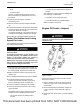
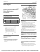

3. Lift the edge of the valve head to a distance of
15 mm (0.591 inch).
4. Move the valve in a radial direction away from the
dial indicator. Make sure that the valve moves
away from the dial indicator as far as possible.
Position the contact point of the dial indicator on
the edge of the valve head. Set the position of the
needle of the dial indicator to zero.
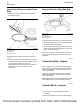
5. Move the valve in a radial direction toward the dial
indicator as far as possible. Note the distance of
movement which is indicated on the dial indicator.
If the distance is greater than the maximum
clearance of the valve in the valve guide, replace
the valve guide. Refer to Specifications, “Cylinder
Head Valves” for the clearances.
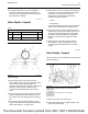
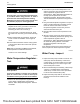
The original valve guides are bored into the cylinder
head. When new valve guides (1) are installed, new
valves and new valve seat inserts must be installed.
The cylinder head must be rebored in order to install
the new valve guide. For more information, contact
your distributor or your dealer.
72 UENR0623-02
Air Inlet and Exhaust System
This document has been printed from SPI2. NOT FOR RESALE