
User Manual

7. If an engine valve lash is found in any position,
examine the valve mechanism components for
excessive wear or damage. Examine the hydraulic
lash adjusters for damage.
i04215789
Valve Depth - Inspect
Table 8
Required Tools
Tool Part Number
Part Description Qty
A 21825617
Dial gauge
1
B 21825496
Dial gauge holder
1
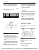
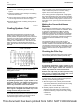
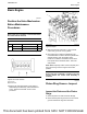
Illustration 61 g01201916
Typical example
1. Ensure that the face of the valves are clean.
Ensure that the bottom face of the cylinder head is
clean. Ensure that the cylinder head is not
distorted. Refer to Systems Operation, Testing and
Adjusting, “Cylinder Head - Inspect” for the
procedure to measure flatness of the cylinder
head.
2. Use the Tooling (A) to check the depths of the inlet
valves and the exhaust valves below the face of
the cylinder head. Use Tooling (B) to zero Tooling
(A).
3. For the minimum and maximum limits for a new
engine for the inlet valves and the exhaust valves,
refer to Specifications, “Cylinder Head”.
4. Service wear occurs on an engine which has been
in operation. If the valve depth below the cylinder
head face on a used engine exceeds the
specification for service wear, the following
components must be replaced.
• Valves
• Valve inserts
For the wear limits for the inlet valves and exhaust
valves, refer to Specifications, “Cylinder Head”.
5. Check each valve for cracks. Check the stems of
the valves for wear. Ensure that the valves are the
correct fit in the valve guides. Refer to Systems
Operation, Testing and Adjusting, “Valve Guide -
Inspect” for the procedure to inspect the valve
guides.
6. Check the load on the valve springs. Refer to
Specifications, “Cylinder Head Valves” for the
correct lengths and specifications for the valve
springs.
i04483849
Valve Guide - Inspect
Perform this test in order to determine if a valve guide
should be replaced.
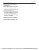
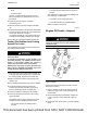
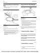
Illustration 62 g00314806
Measure the radial movement of the valve in the
valve guide.
(1) Valve guide
(2) Radial movement of the valve in the valve guide
(3) Valve stem
(4) Dial indicator
(5) Valve head
1. Place a new valve in the valve guide.
2. Place a dial indicator with a magnetic base on the
face of the cylinder head.
UENR0623-02 71
Air Inlet and Exhaust System
This document has been printed from SPI2. NOT FOR RESALE