
User Manual

1. If necessary, remove the accessory drive. Refer to
Disassembly and Assembly, “Accessory Drive -
Remove and Install” for the correct procedure.
Remove plug (1) from the engine. Use Tooling (A)
in order to rotate the crankshaft in the normal
direction of rotation.
2. Install Tooling (B) into Hole (X) in the engine. Use
Tooling (B) in order to locate the camshaft in the
correct position.
Note: Do not use excessive force to install Tooling
(B). Do not use Tooling (B) to hold the camshaft
during repairs.
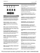
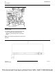
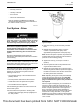
3. If the shaft for the fuel injection pump is not in the
position shown in illustration 51 , the timing of the
fuel injection pump may be incorrect. If necessary,
remove the fuel injection pump. Refer to
Disassembly and Assembly for the correct
procedure.
Illustration 51 g02906337
Typical example
4. Ensure that the camshaft is in correct position. If
necessary, install the fuel injection pump. Refer to
Disassembly and Assembly for the correct
procedure. Ensure that the fuel injection pump
shaft is in the correct position as shown in
illustration 51 . The Angle (Y) should be 45
degrees.
5. If necessary, remove Tooling (B). Install plug (1) to
the engine.
6. If necessary, install the accessory drive . Refer to
Disassembly and Assembly, “Accessory Drive -
Remove and Install” for the correct procedure.
i04338389
Fuel Quality - Test
Note: Refer to Systems Operation, Testing and
Adjusting, “Cleanliness of Fuel System
Components” for detailed information on the
standards of cleanliness that must be observed
during ALL work on the fuel system.
Ensure that all adjustments and repairs are
performed by authorized personnel that have had the
correct training.
Use the following procedure to test for problems
regarding fuel quality:
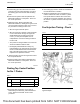
1. Determine if water and/or contaminants are
present in the fuel. Check the water separator.
Drain the water separator, if necessary. A full fuel
tank minimizes the potential for overnight
condensation.
Note: A water separator can appear to be full of fuel
when the water separator is full of water.
2. Determine if contaminants are present in the fuel.
Remove a sample of fuel from the bottom of the
fuel tank. Visually inspect the fuel sample for
contaminants. The color of the fuel is not
necessarily an indication of fuel quality. However,
fuel that is black, brown, and/or like sludge can be
an indication of the growth of bacteria or oil
contamination. In cold temperatures, cloudy fuel
indicates that the fuel may not be suitable for
operating conditions.
Refer to Operation and Maintenance Manual,
“Fuel Recommendations” for more information.
3. If fuel quality is still suspected as a possible cause
to problems regarding engine performance,
disconnect the fuel inlet line. Temporarily operate
the engine from a separate source of fuel that is
known to be good. This will determine if the
problem is caused by fuel quality. If fuel quality is
determined to be the problem, drain the fuel
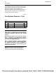
system and replace the fuel filters. Engine
performance can be affected by the following
characteristics:
• Cetane number of the fuel
58 UENR0623-02
Fuel System
This document has been printed from SPI2. NOT FOR RESALE